
Related Manuals for Adafruit ESP32-S2 Feather

Summary of Contents for Adafruit ESP32-S2 Feather
- Page 1 Adafruit ESP32-S2 Feather Created by Kattni Rembor https://learn.adafruit.com/adafruit-esp32-s2-feather Last updated on 2023-08-29 03:30:56 PM EDT ©Adafruit Industries Page 1 of 297...
- Page 2 • What Happens When My Code Finishes Running? • What if I Don't Have the Loop? Connecting to the Serial Console • Are you using Mu? • Serial Console Issues or Delays on Linux ©Adafruit Industries Page 2 of 297...
- Page 3 Entering the REPL • Interacting with the REPL • Returning to the Serial Console CircuitPython Libraries • The Adafruit Learn Guide Project Bundle • The Adafruit CircuitPython Library Bundle • Downloading the Adafruit CircuitPython Library Bundle • The CircuitPython Community Library Bundle •...
- Page 4 • Copy Files on MacOS Without Creating Hidden Files • Other MacOS Space-Saving Tips • Device Locked Up or Boot Looping Welcome to the Community! • Adafruit Discord • CircuitPython.org • Adafruit GitHub • Adafruit Forums • Read the Docs...
- Page 5 • MAX17048 Simple Data Example I2C: On-Board Sensors • Sensor Location • BME280 and LC709203 Simple Data Example • BME280 and LC709203 Adafruit IO Example • Adafruit IO Example Secrets • Adafruit IO Example Code • Customisation • Code Walk-Through CircuitPython Internet Test •...
- Page 6 Arduino Library Installation • LC709203 Simple Data Example MAX17048 Simple Data • Arduino Library Installation • MAX17048 Simple Data Example WiFi Test • WiFi Connection Test • Secure Connection Example • JSON Parsing Demo ©Adafruit Industries Page 6 of 297...
- Page 7 • Adafruit IO Setup • Code Usage WipperSnapper Setup • What is WipperSnapper • Sign up for Adafruit.io • Add a New Device to Adafruit IO • Feedback • Troubleshooting • "Uninstalling" WipperSnapper WipperSnapper Usage • Blink a LED •...
- Page 8 Going Further Monitor Battery (LC709203F) • Where is the Battery Monitor on my Feather? • Powering the Feather with a Battery • Add Battery Monitor Component to Adafruit IO • Going Further Factory Reset • Factory Reset Firmware UF2 •...
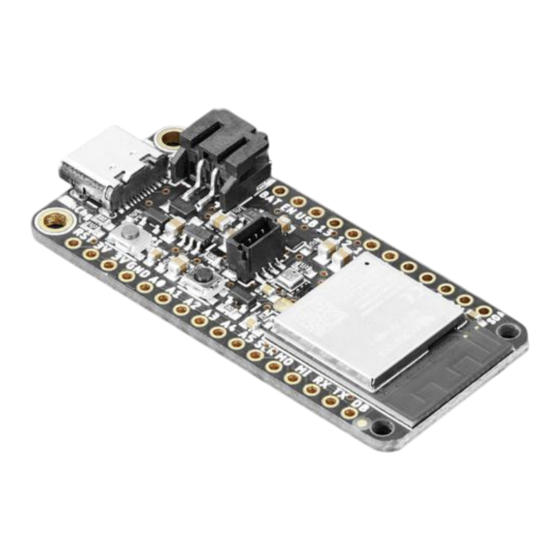
- Page 9 Espressif WiFi microcontroller and lots of Flash and RAM memory for your next IoT project? What will make your next IoT project sensor project flyyyyy? That's right - it's the new Adafruit ESP32-S2 Feather and Adafruit ESP32-S2 Feather with BME280! With native USB and 4 MB flash + 2 MB of PSRAM, these boards are perfect for use with CircuitPython or Arduino with low-cost WiFi.
- Page 10 Things (IoT) (), wearable electronics (), and smart homes. Please note the Feather ESP32-S2 has a single-core 240 MHz chip, so it won't be as fast as ESP32's with dual-core. Also, there is no Bluetooth support. However, we are ©Adafruit Industries Page 10 of 297...
- Page 11 On/Charge/User LEDs + status NeoPixel with pin-controlled power for low power usage • Low Power friendly! In deep sleep mode we can get down to 30uA of current draw from the Lipoly connection. Quiescent current is from the power regulator, ©Adafruit Industries Page 11 of 297...
- Page 12 ESP32-S2 chip, and Lipoly monitor. Turn off the NeoPixel and external I2C power for the lowest quiescent current draw. • Works with Arduino or CircuitPython Pinouts Link to PrettyPins PDF GitHub (). ©Adafruit Industries Page 12 of 297...
- Page 13 EN - This is the 3.3V regulator's enable pin. It's pulled up, so connect to ground to disable the 3.3V regulator. • 3.3V - These pins are the output from the 3.3V regulator, they can supply 500mA peak. ©Adafruit Industries Page 13 of 297...
- Page 14 (this includes two OTA option spots as well) and a 1MB section for CircuitPython scripts and files. Battery Monitor Depending on when you purchased your ESP32-S2 Feather, you may have either the LC709203 or MAX17048 battery monitor onboard. Check the back silkscreen of your Feather to see which one you have.
- Page 15 LC709203 to the MAX17048. Check the back silkscreen of your Feather to see which chip you have. LC709203 Battery Monitor The Adafruit LC709203F LiPoly / LiIon Fuel Gauge and Battery Monitor reports the voltage and charge percent over I2C. Connect it to your Lipoly or LiIon battery ()
- Page 16 This pin must be pulled high for the sensor and stemma QT port to work. This is done automatically by CircuitPython and Arduino. It is available in CircuitPython as , and in Arduino as I2C_POWER PIN_I2C_POWER ©Adafruit Industries Page 16 of 297...
- Page 17 The version of the Feather ESP32-S2 without the BME280 has an unpopulated header in the center where the sensor would go. The BME280 is only available on the Adafruit ESP32-S2 Feather with BME280 Sensor! If you purchased the version without the BME280, your board will not have one.
- Page 18 and board.SCL , or rd.SDA board.STEMMA_I2C() • There is an I2C power pin that needs to be pulled high for the STEMMA QT connector and the BME280 sensor (if present) to work properly. CircuitPython ©Adafruit Industries Page 18 of 297...
- Page 19 • There is a NeoPixel power pin that needs to be pulled high for the NeoPixel to work. This is done automatically by CircuitPython and Arduino. It is available in CircuitPython and Arduino as NEOPIXEL_POWER ©Adafruit Industries Page 19 of 297...
- Page 20 If you run into I2C or TFT power issues on Arduino, ensure you are using the latest Espressif board support package. If you are still having issues, you may need to manually pull the pin HIGH in your code. ©Adafruit Industries Page 20 of 297...
- Page 21 This button can also be used to put the board into ROM bootloader mode. To enter ROM bootloader mode, hold down DFU button while clicking reset button mentioned above. When in the ROM bootloader, you can upload code and query the chip using esptool Debug ©Adafruit Industries Page 21 of 297...
- Page 22 (LiIon) battery to the JST jack. This will let the Feather run on a rechargeable battery. When the USB power is powered, it will automatically switch over to USB for power, as well as start charging the battery (if attached). This happens 'hot-swap' style so you ©Adafruit Industries Page 22 of 297...
- Page 23 LiPoly connected as a 'backup' power that will only get used when USB power is lost. The JST connector polarity is matched to Adafruit LiPoly batteries. Using wrong polarity batteries can destroy your Feather. Many customers try to save money...
- Page 24 (mAh of the battery which helps tune the calculation), and read the voltage and percentage whenever you like. There is no pin on this board that returns battery voltage, but this I2C monitor makes it super simple to get that data! ©Adafruit Industries Page 24 of 297...
- Page 25 In Arduino, you can measure the battery voltage using the following script. // SPDX-FileCopyrightText: 2023 Liz Clark for Adafruit Industries // SPDX-License-Identifier: MIT // Adafruit Battery Monitor Demo // Checks for MAX17048 or LC709203F #include <Wire.h> #include "Adafruit_MAX1704X.h" #include "Adafruit_LC709203F.h"...
- Page 26 Serial.println(" V"); Serial.print(F("Batt Percent: ")); Serial.print(maxlipo.cellPercent(), 1); Serial.println(" %"); Serial.println(); For CircuitPython, you can measure it like this. # SPDX-FileCopyrightText: Copyright (c) 2023 Kattni Rembor for Adafruit Industries # SPDX-License-Identifier: Unlicense import time import board from adafruit_max1704x import MAX17048 from adafruit_lc709203f import LC709203F, PackSize i2c = board.I2C()
- Page 27 If you run into I2C or NeoPixel power issues on Arduino, ensure you are using the latest Espressif board support package. If you are still having issues, you may need to manually pull the pin high in your code. ©Adafruit Industries Page 27 of 297...
- Page 28 Feathers/Wings use those pins for high current usages. You may end up damaging your Feather. • Connect an external 5V power supply to the USB and GND pins. Not recommended, this may cause unexpected behavior when plugging in the USB ©Adafruit Industries Page 28 of 297...
- Page 29 Follow this step-by-step to quickly get CircuitPython running on your board. Download the latest version of CircuitPython for this board via circuitpython.org Click the link above to download the latest CircuitPython UF2 file. Save it wherever is convenient for you. ©Adafruit Industries Page 29 of 297...
- Page 30 If after several tries, and verifying your USB cable is data-ready, you still cannot get to the bootloader, it is possible that the bootloader is missing or damaged. Check out the Install UF2 Bootloader page for details on resolving this issue. ©Adafruit Industries Page 30 of 297...
- Page 31 Install UF2 Bootloader If your board has a UF2 bootloader, you do not need to follow the steps on this page. Try to enter the UF2 bootloader before continuing! Double-tap the reset button to do so. ©Adafruit Industries Page 31 of 297...
- Page 32 The Adafruit ESP32-S2 Feather ships with a UF2 bootloader which allows the board to show up as FTHRS2BOOT when you double-tap the reset button, and enables you to drag and drop UF2 files to update the firmware. On ESP32-S2/S3, there is no bootloader protection for the UF2 bootloader. That means it is possible to erase or damage the UF2 bootloader, especially if you upload an Arduino sketch to an ESP32-S2/S3 board that doesn't "know"...
- Page 33 "gear" icon. If the mode says "Microbit" or something else, click the Mode button in the upper left, and then choose "CircuitPython" in the dialog box that appears. ©Adafruit Industries Page 33 of 297...
- Page 34 You can edit your code directly on this drive and when you save, it will run automatically. When you create and edit code, you'll save your code in a code.py file located on the CIRCUITPY drive. If you're following along with a Learn guide, you can ©Adafruit Industries Page 34 of 297...
- Page 35 The web workflow provides browser-based WiFi access to the CircuitPython filesystem. These guides will help you with the web workflow: • CircuitPython on ESP32 Quick Start () • CircuitPython Web Workflow Code Editor Quick Start () ©Adafruit Industries Page 35 of 297...
- Page 36 This section covers how to create and edit your first CircuitPython program. To create and edit code, all you'll need is an editor. There are many options. Adafruit strongly recommends using Mu! It's designed for CircuitPython, and it's really simple and easy to use, with a built in serial console! If you don't or can't use Mu, there are a number of other editors that work quite well.
- Page 37 The little LED should now be blinking. Once per half-second. Congratulations, you've just run your first CircuitPython program! On most boards you'll find a tiny red LED. On the ItsyBitsy nRF52840, you'll find a tiny blue LED. ©Adafruit Industries Page 37 of 297...
- Page 38 If you are dragging a file from your host computer onto the CIRCUITPY drive, you still need to do step 2. Eject or Sync (below) to make sure the file is completely written. ©Adafruit Industries Page 38 of 297...
- Page 39 Leave the rest of the code as-is. Save your file. See what happens to the LED on your board? Something changed! Do you know why? You don't have to stop there! Let's keep going. Change the second so it looks like this: while True: led.value = True ©Adafruit Industries Page 39 of 297...
- Page 40 First, you'll take a look at the code you're editing. Here is the original code again: import board import digitalio import time led = digitalio.DigitalInOut(board.LED) led.direction = digitalio.Direction.OUTPUT while True: led.value = True time.sleep(0.5) led.value = False time.sleep(0.5) ©Adafruit Industries Page 40 of 297...
- Page 41 "true" (vs. false), and as is never False, the code will loop forever. True All code that is indented under is "inside" the loop. while True: Inside our loop, you have four items: ©Adafruit Industries Page 41 of 297...
- Page 42 If you don't have the loop, the code will run to the end and exit. This can lead to some unexpected behavior in simple programs like this since the "exit" also resets the state of the hardware. This is a different behavior than running commands via REPL. So if ©Adafruit Industries Page 42 of 297...
- Page 43 A terminal is a program that gives you a text-based interface to perform various tasks. Are you using Mu? If so, good news! The serial console is built into Mu and will autodetect your board making using the serial console really really easy. ©Adafruit Industries Page 43 of 297...
- Page 44 "AT" and other gibberish when you connect, then the service might be interfering. Just remove it; it doesn't have much use modemmanager unless you're still using dial-up modems. To remove , type the following command at a shell: modemmanager ©Adafruit Industries Page 44 of 297...
- Page 45 Linux has a terminal program built in, though other options are available for download. Check the Advanced Serial Console on Linux page for more details. () Once connected, you'll see something like the following. ©Adafruit Industries Page 45 of 297...
- Page 46 Now, let's go take a look at the window with our connection to the serial console. Excellent! Our print statement is showing up in our console! Try changing the printed text to something else. import board import digitalio import time ©Adafruit Industries Page 46 of 297...
- Page 47 Save your file. You will notice that your red LED will stop blinking, and you may have a colored status LED blinking at you. This is because the code is no longer correct and can no longer run properly. You need to fix it! ©Adafruit Industries Page 47 of 297...
- Page 48 Nice job fixing the error! Your serial console is streaming and your red LED Is blinking again. The serial console will display any output generated by your code. Some sensors, such as a humidity sensor or a thermistor, receive data and you can use print ©Adafruit Industries Page 48 of 297...
- Page 49 If your code.py file is empty or does not contain a loop, it will show an empty output . There is no information about what your board was Code done running. doing before you interrupted it because there is no code running. ©Adafruit Industries Page 49 of 297...
- Page 50 . This will tell you where to start exploring the REPL. To run code in the help() REPL, type it in next to the REPL prompt. Type next to the prompt in the REPL. help() ©Adafruit Industries Page 50 of 297...
- Page 51 In this case, it's telling the REPL that you plan to do something with that module. Next, type into the REPL and press enter. dir(board) ©Adafruit Industries Page 51 of 297...
- Page 52 So be sure to save any desired code you wrote somewhere else, or you'll lose it when you leave the current REPL instance! ©Adafruit Industries Page 52 of 297...
- Page 53 You can return to the REPL at any time! CircuitPython Libraries As CircuitPython development continues and there are new releases, Adafruit will stop supporting older releases. Visit https://circuitpython.org/downloads to download the latest version of CircuitPython for your board. You must download the CircuitPython Library Bundle that matches your version of CircuitPython.
- Page 54 The Adafruit Learn Guide Project Bundle The quickest and easiest way to get going with a project from the Adafruit Learn System is by utilising the Project Bundle. Most guides now have a Download Project Bundle button available at the top of the full code example embed. This button downloads all the necessary files, including images, etc., to get the guide project up...
- Page 55 Piano in the Key of Lime guide. The Piano in the Key of Lime guide was chosen as an example. That guide is specific to Circuit Playground Express, and cannot be used on all boards. Do not ©Adafruit Industries Page 55 of 297...
- Page 56 Library Bundle. The bundle contains all the files needed to use each library. Downloading the Adafruit CircuitPython Library Bundle You can download the latest Adafruit CircuitPython Library Bundle release by clicking the button below. The libraries are being constantly updated and improved, so you'll always want to download the latest bundle. ...
- Page 57 CircuitPython community. These libraries are often written when community members encountered hardware not supported in the Adafruit Bundle, or to support a personal project. The authors all chose to submit these libraries to the Community Bundle make them available to the community.
- Page 58 All example files from each library are now included in the bundles in an examples directory (as seen above), as well as an examples-only bundle. These are included for two main reasons: • Allow for quick testing of devices. ©Adafruit Industries Page 58 of 297...
- Page 59 First up: the best place to start. When you look at most CircuitPython examples, you'll see they begin with one or more statements. These typically look like the following: import • import library_or_module ©Adafruit Industries Page 59 of 297...
- Page 60 The following is the list of modules built into CircuitPython for the Feather RP2040. Your list may look similar or be anything down to a significant subset of this list for smaller boards. ©Adafruit Industries Page 60 of 297...
- Page 61 That is how you can use your example code to figure out what libraries to load on your CircuitPython-compatible board! ©Adafruit Industries Page 61 of 297...
- Page 62 = simpleio.DigitalOut(board.LED) while True: led.value = True time.sleep(0.5) led.value = False time.sleep(0.5) Save this file. Nothing happens to your board. Let's check the serial console to see what's going on. ©Adafruit Industries Page 62 of 297...
- Page 63 To update a single library or example, follow the same steps above. When you drag the library file to your lib folder, it will ask if you want to replace it. Say yes. That's it! ©Adafruit Industries Page 63 of 297...
- Page 64 CircuitPython core and related topics. It includes API and usage info, a design guide and information about porting CircuitPython to new boards, MicroPython info with relation to CircuitPython, and general information about the project. ©Adafruit Industries Page 64 of 297...
- Page 65 The fourth and final section is About the Project. It includes further information including details on building, testing, and debugging CircuitPython, along with various other useful links including the Adafruit Community Code of Conduct. Whether you're a seasoned pro or new to electronics and programming, you'll find a...
- Page 66 CircuitPython Library Documentation The Adafruit CircuitPython libraries are documented in a very similar fashion. Each library has its own page on Read the Docs. There is a comprehensive list available e (). Otherwise, to view the documentation for a specific library, you can visit the GitHub repository for the library, and find the link in the README.
- Page 67 The LED Animation documentation includes a series of examples, all of which are available in the library. These examples include demonstrations of both basic and more complex features. Simply click on the example that interests you to view the associated code. ©Adafruit Industries Page 67 of 297...
- Page 68 When you click on an item in the API Reference section, you'll find details about the classes and functions in the library. In the case of only one item in this section, all the ©Adafruit Industries Page 68 of 297...
- Page 69 You may be interested in something a little more practical. Here is an example. To use the LED Animation library Comet animation, you would run the following example. # SPDX-FileCopyrightText: 2021 Kattni Rembor for Adafruit Industries # SPDX-License-Identifier: MIT """...
- Page 70 This type of information is available for any function you would set up in your code. If you need clarification on something, wonder whether there's more options available, or are simply interested in the details involved in the code you're writing, check out the documentation for the CircuitPython libraries! ©Adafruit Industries Page 70 of 297...
- Page 71 This section is the same for every library. It includes a list of links to external sites, which you can visit for more information about the CircuitPython Project and Adafruit. That covers the CircuitPython library documentation! When you are ready to go...
- Page 72 You are strongly encouraged to upgrade to Windows 10 if you are still using Windows 7 or Windows 8 or 8.1. Windows 7 has reached end-of-life and no longer receives security updates. A free upgrade to Windows 10 is still available (). ©Adafruit Industries Page 72 of 297...
- Page 73 (COM#) after it where # is a number. Now plug in your board. The Device Manager list will refresh and a new item will appear under Ports (COM & LPT). You'll find a different (COM#) after this item in the list. ©Adafruit Industries Page 73 of 297...
- Page 74 USB it doesn't matter so much but for ESP8266 and other board with a separate chip, the speed required by the board is 115200 bits per second. So you might as well just use 115200! ©Adafruit Industries Page 74 of 297...
- Page 75 "Open" at the bottom of the window. A new window will open. If no code is running, the window will either be blank or will look like the window above. Now you're ready to see the results of your code. ©Adafruit Industries Page 75 of 297...
- Page 76 In this case, you're asking to see all of the listings in that start with /dev/ and end in anything. This will show us the current serial connections. Now, plug your board. In Terminal, type: ls /dev/tty.* ©Adafruit Industries Page 76 of 297...
- Page 77 The baud rate is the speed in bits per second that data is sent over the serial connection. In this case, the speed required by the board is 115200 bits per second. ©Adafruit Industries Page 77 of 297...
- Page 78 Each serial connection shows up in the /dev/ directory. It has a name that starts with tt yACM. The command shows you a list of items in a directory. You can use as a wildcard, to search for files that start with the same letters but end in something ©Adafruit Industries Page 78 of 297...
- Page 79 Now that you know the name your board is using, you're ready connect to the serial console. You'll use a command called . You may need to install it using the screen package manager. ©Adafruit Industries Page 79 of 297...
- Page 80 There are generally two ways you can do this. The first is to just run using the command, which temporarily screen sudo gives you elevated privileges. ©Adafruit Industries Page 80 of 297...
- Page 81 After you log in again, verify that you have been added to the group using the command . If you are still not in the group, reboot and groups check again. And now you should be able to run without using screen sudo ©Adafruit Industries Page 81 of 297...
- Page 82 Circuit Playground Bluefruit () Using Older Versions As CircuitPython development continues and there are new releases, Adafruit will stop supporting older releases. Visit https://circuitpython.org/downloads to download the latest version of CircuitPython for your board. You must download the CircuitPython Library Bundle that matches your version of CircuitPython.
- Page 83 Boards without long integer support are mostly SAMD21 ("M0") boards without an external flash chip, such as the Adafruit Gemma M0, Trinket M0, QT Py M0, and the Trinkey series. There are also a number of third-party boards in this category.
- Page 84 MacroPad or NeoTrellis do not have enough available pins to add the hardware support. For further project examples, and guides about using AirLift with specific hardware, check out the Adafruit Learn System (). How do I do BLE (Bluetooth Low Energy) with CircuitPython? The nRF52840 and nRF52833 boards have the most complete BLE implementation.
- Page 85 Are there other ways to communicate by radio with CircuitPython? Check out Adafruit's RFM boards ()for simple radio communication supported by CircuitPython, which can be used over distances of 100m to over a km, depending on the version. The RFM SAMD21 M0 boards can be used, but they were not designed for CircuitPython, and have limited RAM and flash space;...
- Page 86 ./mpy-cross path/to/yourfile.py yourfile.mpy in the same directory as the original file. How do I check how much memory I have free? Run the following to see the number of bytes available for use: ©Adafruit Industries Page 86 of 297...
- Page 87 Issues list on github (). Adafruit considers CircuitPython for the ESP32-S2 to be beta quality software. I2C at 100 kHz bus frequency runs slowly The default I2C bus clock speed is 100 kHz (100000) . At that rate, the ESP32-S2 will leave 10ms ()
- Page 88 1 or 2 buttons can be selected to wake the MagTag. Troubleshooting From time to time, you will run into issues when working with CircuitPython. Here are a few things you may encounter and how to resolve them. ©Adafruit Industries Page 88 of 297...
- Page 89 I have to continue using CircuitPython 5.x or earlier. Where can I find compatible libraries? Adafruit is no longer building or supporting the CircuitPython 5.x or earlier library bundles. You are highly encourged to update CircuitPython to the latest version ()
- Page 90 Windows 10 Did you install the Adafruit Windows Drivers package by mistake, or did you upgrade to Windows 10 with the driver package installed? You don't need to install this package on Windows 10 for most Adafruit boards. The old version (v1.5) can interfere with recognizing your device.
- Page 91 Let us know in the Adafruit support forums () or on the Adafruit Discord () if this does not work for you! Windows Explorer Locks Up When Accessing boardnameBOOT Drive On Windows, several third-party programs that can cause issues. The symptom is that you try to access the boardnameBOOT drive, and Windows or Windows Explorer...
- Page 92 Serial Console in Mu Not Displaying Anything There are times when the serial console will accurately not display anything, such as, when no code is currently running, or when code with no serial output is already ©Adafruit Industries Page 92 of 297...
- Page 93 CIRCUITPY drive. This feature is called auto-reload, and lets you test a change to your program immediately. Some utility programs, such as backup, anti-virus, or disk-checking apps, will write to the CIRCUITPY as part of their operation. Sometimes they do this very frequently, causing constant restarts. ©Adafruit Industries Page 93 of 297...
- Page 94 Once started, CircuitPython will blink a pattern every 5 seconds when no user code is running to indicate why the code stopped: • 1 GREEN blink: Code finished without error. • 2 RED blinks: Code ended due to an exception. Check the serial console for details. ©Adafruit Industries Page 94 of 297...
- Page 95 Colors with multiple flashes following indicate a Python exception and then indicate the line number of the error. The color of the first flash indicates the type of error: • GREEN: IndentationError • CYAN: SyntaxError • WHITE: NameError ©Adafruit Industries Page 95 of 297...
- Page 96 So, for instance, if you upgraded to CircuitPython 7.x from 6.x you’ll need to download a newer version of the library that triggered the error on . All libraries are import available in the Adafruit bundle (). ©Adafruit Industries Page 96 of 297...
- Page 97 CIRCUITPY drive. Therefore, whatever you may have done to put your board in a non-interactive state, safe mode gives you the opportunity to correct it without losing all of the data on the CIRCUITPY drive. ©Adafruit Industries Page 97 of 297...
- Page 98 At this point, you'll want to remove any user code in code.py and, if present, the boot. py file from CIRCUITPY. Once removed, tap the reset button, or unplug and plug in ©Adafruit Industries Page 98 of 297...
- Page 99 The REPL method is explained above. For the specific boards listed below: If the board you are trying to erase is listed below, follow the steps to use the file to erase your board. ©Adafruit Industries Page 99 of 297...
- Page 100 4. The status LED will turn yellow or blue, indicating the erase has started. 5. After approximately 15 seconds, the status LED will light up green. On the NeoTrellis M4 this is the first NeoPixel on the grid ©Adafruit Industries Page 100 of 297...
- Page 101 4. The boot LED will start flashing again, and the boardnameBOOT drive will reappear. 5. Drag the appropriate latest release CircuitPython () .uf2 file to the boardnameBOOT drive. It should reboot automatically and you should see CIRCUITPY in your file explorer again. ©Adafruit Industries Page 101 of 297...
- Page 102 The file system on the board is very tiny. (Smaller than an ancient floppy disk.) So, its likely you'll run out of space but don't panic! There are a number of ways to free up space. ©Adafruit Industries Page 102 of 297...
- Page 103 Now follow the steps from this question () to run these terminal commands that stop hidden files from being created on the board: mdutil -i off /Volumes/CIRCUITPY cd /Volumes/CIRCUITPY rm -rf .{,_.}{fseventsd,Spotlight-V*,Trashes} mkdir .fseventsd ©Adafruit Industries Page 103 of 297...
- Page 104 Finder because it will still create these hidden extended attribute files in some cases (for files downloaded from the internet, like Adafruit's modules). To copy a file or folder use the -X option for the cp command in a terminal. For example to copy a file_name.mpy file to the board use a command like:...
- Page 105 . The acts as a wildcard to rm CIRCUITPY/._* apply the command to everything that begins with ._ at the same time. Finally, you can run again to see the current space used. ©Adafruit Industries Page 105 of 297...
- Page 106 LED on the second click. For ESP32-S2 based devices: Press and release the reset button, then press and release the boot button about 3/4 of a second later. Refer to the diagrams above for boot sequence details. ©Adafruit Industries Page 106 of 297...
- Page 107 Whether this is your first microcontroller board or you're a seasoned software engineer, you have something important to offer the Adafruit CircuitPython community. This page highlights some of the many ways you can be a part of it! Adafruit Discord ©Adafruit Industries...
- Page 108 The Adafruit Discord server is the best place to start. Discord is where the community comes together to volunteer and provide live support of all kinds. From general discussion to detailed problem solving, and everything in between, Discord is a digital maker space with makers from around the world.
- Page 109 CircuitPython.org Beyond the Adafruit Learn System, which you are viewing right now, the best place to find information about CircuitPython is circuitpython.org (). Everything you need to get started with your new microcontroller and beyond is available. You can do things like download CircuitPython for your microcontroller ()
- Page 110 GitHub pull requests, or PRs, are opened when folks have added something to an Adafruit CircuitPython library GitHub repo, and are asking for Adafruit to add, or merge, their changes into the main library code. For PRs to be merged, they must first be reviewed.
- Page 111 As well, there are always folks available on scord () to answer questions. Library Infrastructure Issues The third tab you'll find is a list of library infrastructure issues. ©Adafruit Industries Page 111 of 297...
- Page 112 CircuitPython contributions, folks are there to help. Regardless of your skill level, or how you want to contribute to the CircuitPython project, there is an opportunity available. The Contributing page () is an excellent place to start! ©Adafruit Industries Page 112 of 297...
- Page 113 Adafruit GitHub Whether you're just beginning or are life-long programmer who would like to contribute, there are ways for everyone to be a part of the CircuitPython project. The CircuitPython core is written in C. The libraries are written in Python. GitHub is the...
- Page 114 You need an Adafruit account to post to the forums. You can use the same account you use to order from Adafruit.
- Page 115 CircuitPython core and the CircuitPython libraries. This is where you'll find things like API documentation and example code. For an in depth look at viewing and understanding Read the Docs, check out the CircuitPython Documentation () page! ©Adafruit Industries Page 115 of 297...
- Page 116 Some examples require external components, such as switches or sensors. You'll find wiring diagrams where applicable to show you how to wire up the necessary components to work with each example. The following components are needed to complete all of the examples: ©Adafruit Industries Page 116 of 297...
- Page 117 (ha!). This plug-n-play pot comes with a JST-PH 2mm connector and a matching https://www.adafruit.com/product/4493 Adafruit MCP9808 High Accuracy I2C Temperature Sensor Breakout The MCP9808 digital temperature sensor is one of the more accurate/precise we've ever seen, with a typical accuracy of ±0.25°C over the sensor's -40°C to...
- Page 118 CircuitPython you're using and copy the contents of that directory to your CIRCUITPY drive. Your CIRCUITPY drive should now look similar to the following image: # SPDX-FileCopyrightText: 2021 Kattni Rembor for Adafruit Industries # SPDX-License-Identifier: MIT """CircuitPython Blink Example - the CircuitPython 'Hello, World!'"""...
- Page 119 LED as a digital output. You can just as easily set up a digital input such as a button to control the LED. This example builds on the basic Blink example, but now includes setup for a button switch. Instead of using the time ©Adafruit Industries Page 119 of 297...
- Page 120 CircuitPython you're using and copy the contents of that directory to your CIRCUITPY drive. Your CIRCUITPY drive should now look similar to the following image: # SPDX-FileCopyrightText: 2022 Kattni Rembor for Adafruit Industries # SPDX-License-Identifier: MIT """...
- Page 121 Inside the loop, you check to see if the button is pressed, and if so, turn on the LED. Otherwise the LED is off. That's all there is to controlling an LED with a button switch! ©Adafruit Industries Page 121 of 297...
- Page 122 An analog-to-digital-converter, or ADC, is the key to reading analog signals and voltages with a microcontroller. An ADC is a device that reads the voltage of an analog signal and converts it into a digital, or numeric, value. The microcontroller ©Adafruit Industries Page 122 of 297...
- Page 123 By wiring the potentiometer to your board in a special way (called a voltage divider) you can turn the change in resistance into a change in voltage that your board’s analog to digital converter can read. ©Adafruit Industries Page 123 of 297...
- Page 124 Connect the other outside pin to voltage in (e.g. 3.3V) Connect the middle pin to an analog pin (e.g. A0) Hardware In addition to your microcontroller board, you will need the following hardware to follow along with this example. Potentiometer ©Adafruit Industries Page 124 of 297...
- Page 125 CircuitPython_Templates/analog_pin_values/ and then click on the directory that matches the version of CircuitPython you're using and copy the contents of that directory to your CIRCUITPY drive. Your CIRCUITPY drive should now look similar to the following image: ©Adafruit Industries Page 125 of 297...
- Page 126 # SPDX-FileCopyrightText: 2021 Kattni Rembor for Adafruit Industries # SPDX-License-Identifier: MIT """CircuitPython analog pin value example""" import time import board import analogio analog_pin = analogio.AnalogIn(board.A0) while True: print(analog_pin.value) time.sleep(0.1) Now, rotate the potentiometer to see the values change. What do these values mean? In CircuitPython ADC values are put into the range of 16- bit unsigned values.
- Page 127 CIRCUITPY drive. Your CIRCUITPY drive should now look similar to the following image: # SPDX-FileCopyrightText: 2022 Kattni Rembor for Adafruit Industries # SPDX-License-Identifier: MIT """CircuitPython Analog In Voltage Example for ESP32-S2"""...
- Page 128 CircuitPython code. A NeoPixel is what Adafruit calls the WS281x family of addressable RGB LEDs. It contains three LEDs - a red one, a green one and a blue one - along side a driver chip in a tiny package controlled by a single pin.
- Page 129 CircuitPython you're using and copy the contents of that directory to your C IRCUITPY drive. Your CIRCUITPY drive should now look similar to the following image: # SPDX-FileCopyrightText: 2021 Kattni Rembor for Adafruit Industries # SPDX-License-Identifier: MIT ©Adafruit Industries...
- Page 130 LEDs. You save this object to the board variable pixel Then, you set the NeoPixel brightness using the attribute. brightness brightness expects float between . A float is essentially a number with a decimal in it. ©Adafruit Industries Page 130 of 297...
- Page 131 0, you turn the LED off. Common colors include: • red: (255, 0, 0) • green: (0, 255, 0) • blue: (0, 0, 255) • cyan: (0, 255, 255) • purple: (255, 0, 255) ©Adafruit Industries Page 131 of 297...
- Page 132 CircuitPython you're using and copy the contents of that directory to your CIRCUITPY drive. Your CIRCUITPY drive should now look similar to the following image: # SPDX-FileCopyrightText: 2021 Kattni Rembor for Adafruit Industries # SPDX-License-Identifier: MIT """CircuitPython status NeoPixel rainbow example."""...
- Page 133 Be sure to download the 7.2.4 or later version of CircuitPython Feather ESP32-S2 I2C Setup The Feather ESP32-S2 only has one I2C port, also known as , that is on board.I2C() pins SDA and SCL and shared with the STEMMA QT connector. ©Adafruit Industries Page 133 of 297...
- Page 134 (GPIO 7) to an OUTPUT and the opposite of the 'rest state' before accessing the I2C port If you are using 7.2.4 or higher version of CircuitPython for the ESP32-S2 Feather, the I2C port will be automatically activated/powered properly on boot, whether...
- Page 135 This means you can have many different sensors and devices all connected to the same two pins. Both I2C connections require pull-up resistors, and most Adafruit I2C sensors and breakouts have pull-up resistors built in. If you're using one that does not, you'll need to add your own 2.2-10kΩ...
- Page 136 Necessary Hardware You'll need the following additional hardware to complete the examples on this page. Adafruit MCP9808 High Accuracy I2C Temperature Sensor Breakout The MCP9808 digital temperature sensor is one of the more accurate/precise we've ever seen, with a typical accuracy of ±0.25°C over the sensor's -40°C to...
- Page 137 Extract the contents of the zip file, find your CircuitPython version, and copy the matching code.py file to your CIRCUITPY drive. Your CIRCUITPY drive should now look similar to the following image: # SPDX-FileCopyrightText: 2021 Kattni Rembor for Adafruit Industries # SPDX-License-Identifier: MIT """CircuitPython I2C Device Address Scan"""...
- Page 138 You've connected the MCP9808 which has a 7-bit I2C address of 0x18. The result for this sensor is . If no addresses are returned, refer I2C addresses found: ['0x18'] back to the wiring diagrams to make sure you've wired up your sensor correctly. ©Adafruit Industries Page 138 of 297...
- Page 139 CircuitPython version, and copy the matching entire lib folder and code.py file to your CIRCUITPY drive. Your CIRCUITPY drive should now look similar to the following image: # SPDX-FileCopyrightText: 2021 Kattni Rembor for Adafruit Industries # SPDX-License-Identifier: MIT """CircuitPython I2C MCP9808 Temperature Sensor Example"""...
- Page 140 For the ESP32-S2 Feather, you'll need to change the I2C setup to the commented out setup included in the code above. The ESP32-S2 Feather STEMMA QT connector is available on board.STEMMA_I2C() Comment out the current setup line, and uncomment the the ...
- Page 141 # SPDX-FileCopyrightText: 2021-2023 Kattni Rembor for Adafruit Industries # SPDX-License-Identifier: MIT """CircuitPython I2C possible pin-pair identifying script""" import board import busio from microcontroller import Pin def is_hardware_i2c(scl, sda): try: p = busio.I2C(scl, sda) p.deinit() return True except ValueError: return False...
- Page 142 The LC709203 is available over I2C. The LC709203 comes with its own Adafruit CircuitPython library that makes it simple to write code to read data from it. This example will be using, among other things, the Adafruit CircuitPython LC709203F ()
- Page 143 CIRCUITPY drive. Your CIRCUITPY/lib folder should contain at least the following folder and file: • adafruit_register/ • adafruit_lc709203f.mpy # SPDX-FileCopyrightText: 2022 Kattni Rembor for Adafruit Industries # SPDX-License-Identifier: MIT """ CircuitPython Simple Example for LC709203 Sensor """ ©Adafruit Industries...
- Page 144 For more details, check out the guide for the LC709203 (). MAX17048 Battery Monitor If you purchased your ESP32-S2 Feather before June 14, 2023 then your board may not have the MAX17048 battery monitor. Check the back silkscreen to see which chip is on your Feather.
- Page 145 Extract the contents of the zip file, and copy the entire lib folder and the c ode.py file to your CIRCUITPY drive. Your CIRCUITPY/lib folder should contain at least the following folder and file: • adafruit_bus_device/ • adafruit_register/ • adafruit_max1704x.mpy ©Adafruit Industries Page 145 of 297...
- Page 146 For more details, check out the guide for the MAX17048 (). I2C: On-Board Sensors The examples on this page assume you are using the Adafruit Feather ESP32-S2 with BME280. If you are using a Feather ESP32-S2 without BME280, you can ©Adafruit Industries...
- Page 147 The second example takes the sensor data and sends it to Adafruit IO. It is designed to run on battery power and utilises deep sleep to keep the board cool for temperature readings.
- Page 148 CIRCUITPY drive. Your CIRCUITPY/lib folder should contain the following folder and file: • adafruit_bme280/ • adafruit_lc709203f.mpy # SPDX-FileCopyrightText: 2021 Kattni Rembor for Adafruit Industries # SPDX-License-Identifier: Unlicense """ CircuitPython Simple Example for BME280 and LC709203 Sensors """ import time...
- Page 149 BME280 and LC709203 Adafruit IO Example Adafruit IO gives you the option to disconnect the Feather ESP32-S2 from your computer and run it off of USB power or a battery, and still be able to see the data. This example takes the same data printed to the serial console in the example above, and also sends it to Adafruit IO.
- Page 150 "aio_key": "your-super-long-aio-key", Adafruit IO Example Code To run this example, you need to first install the BME280, LC709203F, Adafruit IO, and Adafruit Requests libraries into the lib folder on your CIRCUITPY drive. Then you need to update code.py with the example script.
- Page 151 ImportError: print("WiFi and Adafruit IO credentials are kept in secrets.py, please add them there!") raise # Duration of sleep in seconds. Default is 600 seconds (10 minutes). # Feather will sleep for this duration between sensor readings / sending data to...
- Page 152 # Turn off the LED to indicate data sending is complete. led.value = False # Adafruit IO can fail with multiple errors depending on the situation, so this except is broad. except Exception as e: # pylint: disable=broad-except...
- Page 153 Then, you setup the hardware. The red LED is used to visually indicate when data is being sent to Adafruit IO. The I2C power pin is enabled and pulled low. The BME280 and the LC708203 are both setup using I2C. And finally, the battery pack size is set.
- Page 154 The first function creates an alarm that will trigger after a number of seconds, and then tells the board to sleep until the alarm is triggered. The second function sets up an Adafruit IO feed by first trying to get the feed, and if it does not exist, creating the feed on Adafruit IO.
- Page 155 Adafruit IO. The LED is then turned off to indicate sending data is completed. Finally, the code tells the board to go to sleep for the sleep duration specified at the beginning of your code.
- Page 156 If you have a fresh install of CircuitPython on your board, the initial settings.toml file on your CIRCUITPY drive is empty. To get started, you can update the settings.toml on your CIRCUITPY drive to contain the following code. ©Adafruit Industries Page 156 of 297...
- Page 157 # This is where you store the credentials necessary for your code. # The associated demo only requires WiFi, but you can include any # credentials here, such as Adafruit IO username and key, etc. WIFI_SSID = "your-wifi-ssid" WIFI_PASSWORD = "your-wifi-password"...
- Page 158 . Initial pings can sometimes fail for various reasons. So, if the initial ping is None successful ( ), it will print the echo speed in ms. If the initial ping fails, it is not None ©Adafruit Industries Page 158 of 297...
- Page 159 . This code snippet requests.get obtains the field from a call to the GitHub API. stargazers_count print(f"Fetching and parsing json from {JSON_STARS_URL}") response = requests.get(JSON_STARS_URL) print("-" * 40) print(f"CircuitPython GitHub Stars: {response.json()['stargazers_count']}") print("-" * 40) ©Adafruit Industries Page 159 of 297...
- Page 160 NeoPixel colors. This example shows how to both send data to and receive data from Adafruit IO. It pulls from a "random" number generator and sends the "random" number to Adafruit IO, while simultaneously listening for NeoPixel color data from Adafruit IO.
- Page 161 Once you choose the color picker block, you'll need to connect a feed to it. Check the box next to neopixel. Finally, a Block Settings page will come up. You can add an optional block title here. Then you press Create Block. ©Adafruit Industries Page 161 of 297...
- Page 162 The dashboard should look something like the following. Now that things are set up on the Adafruit IO end, you can continue on to the code on your microcontroller! Adafruit IO settings.toml This example requires you to provide your Wi-Fi credentials, and your Adafruit IO username and key.
- Page 163 Adafruit IO Example Code To run this example, you need to first install the NeoPixel, Adafruit IO, and Adafruit MiniMQTT libraries into the lib folder on your CIRCUITPY drive. Then you need to update code.py with the example script.
- Page 164 Adafruit IO...") io.connect() # Explicitly pump the message loop. io.loop() # Obtain the "random" value, print it and publish it to Adafruit IO every 10 seconds. if (time.monotonic() - timestamp) >= 10: random_number = "{}".format(randint(0, 255)) print("Current 'random' number: {}".format(random_number)) io.publish("random", random_number)
- Page 165 NeoPixel Color Change To change the color of the NeoPixel, go to the NeoPixel Adafruit IO dashboard you created at the beginning, and click on the colored circle in the ColorPicker block. It will bring up the following.
- Page 166 These are included where the except code is likely to fail due to WiFi or Adafruit IO connection failures. WiFi can be finicky, and without these code blocks, if the connection was lost, the code would crash. Instead, it is designed to reset the board and start the code over again to reestablish the connection, regardless of the cause.
- Page 167 Following that are two callback methods. For more details, check out this guide (). The method subscribes to the neopixel feed on Adafruit IO. The connected message callback checks for updates to the neopixel feed, and turns the pixel the color from the feed.
- Page 168 'random' number: {}".format(random_number)) io.publish("random", random_number) timestamp = time.monotonic() If at any time WiFi or Adafruit IO disconnects, the code will print the error to the serial console, and the board will hard reset after 30 seconds. [...] except Exception as e: print("Failed to get or send data, or connect.
- Page 169 0.1 second interval. Releasing the button returns both to their initial states. Wiring The first step is wiring up the NeoPixel rings to your microcontroller. ©Adafruit Industries Page 169 of 297...
- Page 170 The built-in Boot button (highlighted in magenta in the wiring diagram) is ◦ located along the bottom of the board, towards the center. asyncio Example Code Once everything is wired up, the next step is to load the example code onto your microcontroller. ©Adafruit Industries Page 170 of 297...
- Page 171 Extract the contents of the zip file, and copy the entire lib folder and the c ode.py file to your CIRCUITPY drive. # SPDX-FileCopyrightText: Copyright (c) 2022 Dan Halbert for Adafruit Industries # SPDX-FileCopyrightText: Copyright (c) 2022 Kattni Rembor for Adafruit Industries # SPDX-License-Identifier: MIT """...
- Page 172 Your CIRCUITPY/lib folder should contain at least the following folder and files: • asyncio/ • adafruit_ticks.mpy • neopixel.mpy Ring one will light up in a rainbow swirl. Ring two will begin blinking blue at a 0.5 second interval. ©Adafruit Industries Page 172 of 297...
- Page 173 = neopixel.NeoPixel(board.A2, num_pixels, brightness=brightness, auto_write=False) Following set up, you create a class called . This class provides AnimationControls ways to control the animations with asyncio. class AnimationControls: def __init__(self): self.reverse = False ©Adafruit Industries Page 173 of 297...
- Page 174 In terms of the asyncio-specific parts of this code, you'll notice that both of these functions begin with . Every function that contains an must be async def await defined as , to indicate that it's a coroutine. async def ©Adafruit Industries Page 174 of 297...
- Page 175 Finally, function to execute the code within. main() asyncio.run(main()) My program ended? What happened? runs until all the listed tasks have finished. If await.gather(...) gather completes, that means all the tasks listed have finished. ©Adafruit Industries Page 175 of 297...
- Page 176 CircuitPython. This is because CircuitPython cannot write to the filesystem at the same time as your computer. Doing so can lead to filesystem corruption and loss of all content on the drive, so CircuitPython is designed to only allow one at at time. ©Adafruit Industries Page 176 of 297...
- Page 177 The boot.py File The filesystem will NOT automatically be set to read-only on creation of this file! You'll still be able to edit files on CIRCUITPY after saving this boot.py. # SPDX-FileCopyrightText: 2021 Kattni Rembor for Adafruit Industries # SPDX-License-Identifier: Unlicense """...
- Page 178 # SPDX-FileCopyrightText: 2021 Kattni Rembor for Adafruit Industries # SPDX-License-Identifier: Unlicense """ CircuitPython Essentials Storage CP Filesystem code.py file """ import time import board import digitalio import microcontroller led = digitalio.DigitalInOut(board.LED) led.switch_to_output() try: with open("/temperature.txt", "a") as temp_log: while True: # The microcontroller temperature in Celsius.
- Page 179 USB cable and plugging it back in. This will run the code within boot.py and set your board to writable by CircuitPython, and therefore, read-only by the computer. ©Adafruit Industries Page 179 of 297...
- Page 180 Then, restart the board by either hitting the reset button or unplugging USB and plugging it back in. CIRCUITPY should show up on your computer as usual, but now it should be writable by your computer. ©Adafruit Industries Page 180 of 297...
- Page 181 Extract the contents of the zip file, open the directory CircuitPython_Templates/cap_touch_one_pin_ESP32-S2/ and then click on the directory that matches the version of CircuitPython you're using and copy the contents of that directory to your CIRCUITPY drive. ©Adafruit Industries Page 181 of 297...
- Page 182 Your CIRCUITPY drive should now look similar to the following image: Then, connect to the serial console (). # SPDX-FileCopyrightText: 2021 Kattni Rembor for Adafruit Industries # SPDX-License-Identifier: MIT """ CircuitPython Capacitive Touch Pin Example for ESP32-S2. Print to the serial console when one pin is touched.
- Page 183 CircuitPython you're using and copy the contents of that directory to your CIRCUITPY drive. Your CIRCUITPY drive should now look similar to the following image: ©Adafruit Industries Page 183 of 297...
- Page 184 Then, connect to the serial console (). # SPDX-FileCopyrightText: 2021 Kattni Rembor for Adafruit Industries # SPDX-License-Identifier: MIT """ CircuitPython Capacitive Two Touch Pin Example for ESP32-S2 Print to the serial console when a pin is touched. """ import time import board import touchio touch_one = touchio.TouchIn(board.D8)
- Page 185 Extract the contents of the zip file, find your CircuitPython version, and copy the matching code.py file to your CIRCUITPY drive. Your CIRCUITPY drive should now look similar to the following image: # SPDX-FileCopyrightText: 2021-2023 Kattni Rembor for Adafruit Industries # SPDX-License-Identifier: MIT """...
- Page 186 Capacitive touch on the Feather ESP32-S2 is available on a limited set of pins. The pin names in bold match the Feather silk. The pin names in CircuitPython and Arduino are listed after. ©Adafruit Industries Page 186 of 297...
- Page 187 CircuitPython makes it really simple to read this data from the temperature sensor built into the microcontroller. Using the built-in module, you can microcontroller easily read the temperature. ©Adafruit Industries Page 187 of 297...
- Page 188 CircuitPython you're using and copy the contents of that directory to your CIRCUITPY drive. Your CIRCUITPY drive should now look similar to the following image: # SPDX-FileCopyrightText: 2021 Kattni Rembor for Adafruit Industries # SPDX-License-Identifier: MIT """CircuitPython CPU temperature example in Celsius"""...
- Page 189 CircuitPython you're using and copy the contents of that directory to your CIRCUITPY drive. Your CIRCUITPY drive should now look similar to the following image: # SPDX-FileCopyrightText: 2021 Kattni Rembor for Adafruit Industries # SPDX-License-Identifier: MIT """CircuitPython CPU temperature example in Fahrenheit"""...
- Page 190 After you have downloaded and installed the latest version of Arduino IDE, you will need to start the IDE and navigate to the Preferences menu. You can access it from the File menu in Windows or Linux, or the Arduino menu on OS X. ©Adafruit Industries Page 190 of 297...
- Page 191 URLs is comma separated, and you will only have to add each URL once. New Adafruit boards and updates to existing boards will automatically be picked up by the Board Manager each time it is opened. The URLs point to index files that the Board Manager uses to build the list of available &...
- Page 192 Arduino IDE preferences. https://raw.githubusercontent.com/espressif/arduino-esp32/gh-pages/ package_esp32_dev_index.json If you have multiple boards you want to support, say ESP8266 and Adafruit, have both URLs in the text box separated by a comma (,) Once done click OK to save the new preference settings. The next step is to actually install the Board Support Package (BSP). Go to the Tools →...
- Page 193 Select ESP32-S2/S3 Board in Arduino IDE On the Arduino IDE, click: Tools -> Board -> ESP32 Arduino -> Your Adafruit ESP32-S2/S3 board The screenshot shows Metro S2 but you may have a different board. Make sure the name matches the exact product you purchased.
- Page 194 Reset buttons somewhere It should appear under Tools -> Port as ESP32-S2/S3 Dev Module. Do not select any other port than the one that is called "ESP32S2 Dev Module" or "ESP32S3 Dev Module" ©Adafruit Industries Page 194 of 297...
- Page 195 That's it, you will be able to see the red LED blink. You will also see a new serial port created. You may call in your sketch to create the serial port so don't Serial.begin(); forget it, it is not required for other Arduinos or previous ESP boards! ©Adafruit Industries Page 195 of 297...
- Page 196 When all else fails, you can always come back to Blink! We will be blinking the Red LED here, next to the USB port ©Adafruit Industries Page 196 of 297...
- Page 197 In the IDE find the Tools menu. You will use this to select the board. If you switch boards, you must switch the selection! So always double-check before you upload code in a new session. ©Adafruit Industries Page 197 of 297...
- Page 198 = LED_BUILTIN; void setup() { // Some boards work best if we also make a serial connection Serial.begin(115200); // set LED to be an output pin pinMode(led, OUTPUT); void loop() { // Say hi! ©Adafruit Industries Page 198 of 297...
- Page 199 Note that Verifying a sketch is the same as Compiling a sketch - so we will use the words interchangeably During verification/compilation, the computer will do a bunch of work to collect all the libraries and code and the results will appear in the bottom window of the IDE. ©Adafruit Industries Page 199 of 297...
- Page 200 It can assist in nailing down what happened! On success you will see something like this white text output and the message Done compiling. in the message area. ©Adafruit Industries Page 200 of 297...
- Page 201 Often times you will get a warning like this, which is kind of vague: (or whatever port is selected) No device found on COM66 An error occurred while uploading the sketch ©Adafruit Industries Page 201 of 297...
- Page 202 Before continuing we really, really suggest turning on Verbose Upload messages, it will help in this process because you will be able to see what the IDE is trying to do. It's a checkbox in the Preferences menu. ©Adafruit Industries Page 202 of 297...
- Page 203 Once you are in manual bootload mode, go to the Tools menu, and make sure you have selected the bootloader serial port. It is almost certain that the serial port has changed now that the bootloader is enabled ©Adafruit Industries Page 203 of 297...
- Page 204 A lot of sensors, displays, and devices can connect over I2C. I2C is a 2-wire 'bus' that allows multiple devices to all connect on one set of pins so it's very convenient for wiring! ©Adafruit Industries Page 204 of 297...
- Page 205 Are you keeping the total bus length reasonable? I2C was designed for maybe 6" max length. We like to push that with plug-n-play cables, but really please keep them as short as possible! (Only exception is if you're using an active bus extender ()). ©Adafruit Industries Page 205 of 297...
- Page 206 Perform an I2C scan! Install TestBed Library To scan I2C, the Adafruit TestBed library is used. This library and example just makes the scan a little easier to run because it takes care of some of the basics. You will need to add support by installing the library.
- Page 207 { Serial.begin(115200); // Wait for Serial port to open while (!Serial) { delay(10); delay(500); Serial.println("Adafruit I2C Scanner"); #if defined(ARDUINO_ADAFRUIT_QTPY_ESP32S2) || \ defined(ARDUINO_ADAFRUIT_QTPY_ESP32S3_NOPSRAM) || \ defined(ARDUINO_ADAFRUIT_QTPY_ESP32S3) || \ defined(ARDUINO_ADAFRUIT_QTPY_ESP32_PICO) // ESP32 is kinda odd in that secondary ports must be manually // assigned their pins with setPins()! Wire1.setPins(SDA1, SCL1);...
- Page 208 The first thing you'll want to do is get the sensor connected so your board has I2C to talk to. Adafruit MCP9808 High Accuracy I2C Temperature Sensor Breakout The MCP9808 digital temperature sensor is one of the more accurate/precise we've ever seen, with a typical accuracy of ±0.25°C over the sensor's -40°C to...
- Page 209 Since there is only one port, you should not see a 'secondary' I2C scan. The primary scan shows the built in battery monitoring chip on 0xB and also the special 'all call' address on 0x00 (the battery monitoring chip listens there as well) and finally the MCP9808 on 0x18 ©Adafruit Industries Page 209 of 297...
- Page 210 The LC709203 is available over I2C. The sensor comes with its own Adafruit CircuitPython library that makes it simple to write code to read data from it. This example will be using, among other things, the dafruit LC709203F ()
- Page 211 When asked about installing dependencies, click Install all. LC709203 Simple Data Example Click File > Examples > Adafruit LC709203F > LC709203F_demo to open the example. #include "Adafruit_LC709203F.h" Adafruit_LC709203F lc; void setup() { Serial.begin(115200); delay(10); Serial.println("\nAdafruit LC709203F demo"); // For the Feather ESP32-S2, we need to enable I2C power first!
- Page 212 The MAX17048 is available over I2C. The sensor comes with its own Adafruit CircuitPython library that makes it simple to write code to read data from it. This example will be using, among other things, the A...
- Page 213 Arduino Library Installation You can install the necessary libraries from the Library Manager. To open, click Sketch > Include Library > Manage Libraries... Search for MAX17048, and install the Adafruit MAX1704X library. When asked about installing dependencies, click Install all. ©Adafruit Industries...
- Page 214 MAX17048 Simple Data Example Click File > Examples > Adafruit MAX1704X > MAX17048_basic to open the example. #include "Adafruit_MAX1704X.h" Adafruit_MAX17048 maxlipo; void setup() { Serial.begin(115200); while (!Serial) delay(10); // wait until serial monitor opens Serial.println(F("\nAdafruit MAX17048 simple demo")); if (!maxlipo.begin()) { Serial.println(F("Couldnt find Adafruit MAX17048?\nMake sure a battery is...
- Page 215 Thanksfully if you have ESP32 sketches, they'll 'just work' with variations of ESP32. You can find a wide range of examples in the File->Examples->Examples for Adafruit Metro ESP32-S2 subheading (the name of the board may vary so it could be "Example s for Adafruit Feather ESP32 V2"...
- Page 216 ESP32 to not brown out. A skinny USB cable or drained battery can cause issues. WiFi Connection Test Now that you can scan networks around you, its time to connect to the Internet! ©Adafruit Industries Page 216 of 297...
- Page 217 Copy the example below and paste it into the Arduino IDE: // SPDX-FileCopyrightText: 2020 Brent Rubell for Adafruit Industries // SPDX-License-Identifier: MIT Web client This sketch connects to a website (wifitest.adafruit.com/testwifi/index.html) using the WiFi module. This example is written for a network using WPA encryption. For WEP or WPA, change the Wifi.begin() call accordingly.
- Page 218 WiFi SSID and password before uploading this to your board. After you've set it correctly, upload and check the serial monitor. You should see the following. If not, go back, check wiring, power and your SSID/password ©Adafruit Industries Page 218 of 297...
- Page 219 WiFi connection to connect to the Twitter API. Copy and paste it into the Arduino IDE: // SPDX-FileCopyrightText: 2015 Arturo Guadalupi // SPDX-FileCopyrightText: 2020 Brent Rubell for Adafruit Industries // SPDX-License-Identifier: MIT This example creates a client object that connects and transfers data using always SSL.
- Page 220 // if there are incoming bytes available // from the server, read them and print them: while (client.available()) { char c = client.read(); Serial.write(c); bytes++; // if the server's disconnected, stop the client: if (!client.connected()) { Serial.println(); Serial.println("disconnecting from server."); ©Adafruit Industries Page 220 of 297...
- Page 221 As before, update the ssid and password first, then upload the example to your board. Note we use instead of WiFiClientSecure client WiFiClient client; require a SSL connection! This example will connect to a twitter server to download a JSON snippet that says how many followers adafruit has ©Adafruit Industries Page 221 of 297...
- Page 222 Arduino IDE. // SPDX-FileCopyrightText: 2014 Benoit Blanchon // SPDX-FileCopyrightText: 2014 Arturo Guadalupi // SPDX-FileCopyrightText: 2020 Brent Rubell for Adafruit Industries // SPDX-License-Identifier: MIT This example creates a client object that connects and transfers data using always SSL, then shows how to parse a JSON document in an HTTP response.
- Page 223 Serial.print("Attempting to connect to SSID: "); Serial.println(ssid); #if defined(USE_OLED) display.clearDisplay(); display.setCursor(0,0); display.print("Connecting to SSID\n"); display.println(ssid); display.display(); #endif while (WiFi.status() != WL_CONNECTED) { delay(500); Serial.print("."); Serial.println(""); Serial.println("Connected to WiFi"); #if defined(USE_OLED) display.print("...OK!"); display.display(); #endif printWifiStatus(); uint32_t bytes = 0; ©Adafruit Industries Page 223 of 297...
- Page 224 // Extract values JsonObject root_0 = doc[0]; Serial.println(F("Response:")); const char* root_0_screen_name = root_0["screen_name"]; long root_0_followers_count = root_0["followers_count"]; Serial.print("Twitter username: "); Serial.println(root_0_screen_name); Serial.print("Twitter followers: "); Serial.println(root_0_followers_count); #if defined(USE_OLED) display.clearDisplay(); display.setCursor(0,0); display.setTextSize(2); display.println(root_0_screen_name); display.println(root_0_followers_count); display.display(); display.setTextSize(1); #endif ©Adafruit Industries Page 224 of 297...
- Page 225 // print the received signal strength: long rssi = WiFi.RSSI(); Serial.print("signal strength (RSSI):"); Serial.print(rssi); Serial.println(" dBm"); By default it will connect to to the Twitter banner image API, parse the username and followers, and display them. ©Adafruit Industries Page 225 of 297...
- Page 226 The ESP32-S2/S3 is an affordable, all-in-one, option for connecting your projects to the internet using our IoT platform, Adafruit IO (). • For more information and guides about Adafruit IO, check out the Adafruit IO Basics Series. () Install Libraries In the Arduino IDE, navigate to Sketch -> Include Library->Manage Libraries...
- Page 227 When asked to install dependencies, click Install all. Adafruit IO Setup If you do not already have an Adafruit IO account, create one now (). Next, navigate to the Adafruit IO Dashboards page. We'll create a dashboard to visualize and interact with the data being sent between your ESP32-S2/S3 board and Adafruit IO. ...
- Page 228 Click the link to be brought to your new dashboard. We'll want to turn the board's LED on or off from Adafruit IO. To do this, we'll need to add a toggle button to our dashboard. ©Adafruit Industries Page 228 of 297...
- Page 229 In the dashboard settings dropdown, click Create New Block. Select the toggle block. Under My Feeds, enter led as a feed name. Click Create. Choose the led feed to connect it to the toggle block. Click Next step. ©Adafruit Industries Page 229 of 297...
- Page 230 Change Button Off Text to 0 Click Create block Next up, we'll want to display button press data from your board on Adafruit IO. To do this, we'll add a gauge block to the Adafruit IO dashboard. A gauge is a read only block type that shows a fixed range of values.
- Page 231 In the dashboard settings dropdown, click Create New Block. Select the gauge block. Under My Feeds, enter button as a feed name. Click Create. Choose the button feed to connect it to the toggle block. Click Next step. ©Adafruit Industries Page 231 of 297...
- Page 232 Code Usage For this example, you will need to open the adafruitio_26_led_btn example included with the Adafruit IO Arduino library. In the Arduino IDE, navigate to File -> Examples -> Adafruit IO Arduino -> adafruitio_26_led_btn. Before uploading this code to the ESP32-S2/S3, you'll need to add your network and Adafruit IO credentials.
- Page 233 Click the Upload button to upload your sketch to the ESP32-S2/S3. After uploading, pr ess the RESET button on your board to launch the sketch. Open the Arduino Serial monitor and navigate to the Adafruit IO dashboard you created. You should see the gauge response to button press and the board's LED light up in response to the Toggle Switch block.
- Page 234 Sign up for Adafruit.io You will need an Adafruit IO account to use WipperSnapper on your board. If you do not already have one, head over to io.adafruit.com () to create a free account.
- Page 235 After clicking New Device, you should be on the board selector page. This page displays every board that is compatible with the WipperSnapper firmware. In the board selector page's search bar, search for the ESP32-S2 Feather. Once you've located the board you'd like to install WipperSnapper on, click the Choose Board button to bring you to the self-guided installation wizard.
- Page 236 If the installation was successful, a popover should appear displaying that your board has successfully been detected by Adafruit IO. Give your board a name and click "Continue to Device Page". You should be brought to your board's device page.
- Page 237 If you're still unable to resolve the issue, or if your issue is not listed below, get in touch with us directly at https://io.adafruit.com/support (). Make sure to click "Contact Adafruit IO Support" and select "There is an issue with WipperSnapper. Something is broken!"...
- Page 238 "uninstall". However, you may want to "move" your board from running WipperSnapper to running Arduino or CircuitPython. You also may need to restore your board to the state it was shipped to you from the Adafruit factory. Moving from WipperSnapper to CircuitPython...
- Page 239 (or off) the LED built into your Feather from anywhere in the world. In this demo, we show controlling an LED from Adafruit IO. But the same kind of control can be used for relays, lights, motors, or solenoids.
- Page 240 Verify that your Feather is online and ready to communicate with Adafruit IO by checking that the device tile says Online in green text. • If the Feather appears offline on the website but was previously connected, press the Reset (RST) button to force the board to reboot.
- Page 241 LED on your Feather as a digital output so you can turn the LED on or off. The Feather ESP32-S2 has a built-in LED located at pin D13. Select this pin as the LED Pin and click Create Component ©Adafruit Industries Page 241 of 297...
- Page 242 Behind the scenes, Adafruit IO sends send a command to your board running WipperSnapper telling it to configure the GPIO pin as a digital output. Your Feather's page shows the new LED component. From the page, toggle the LED component by clicking the toggle switch. This should turn your Feather's built-in LED on or off.
- Page 243 Adafruit IO. Let's wire up a push button to your Feather and configure it with Adafruit IO to publish a value to Adafruit IO when the button has been pressed or depressed. ...
- Page 244 + New Component button. From the component picker, select the Push Button. The next screen presents you with options for configuring the push button. Start by selecting the Feather's digital pin you connected to the push button. ©Adafruit Industries Page 244 of 297...
- Page 245 The Return Interval dictates how frequently the value of the push-button will be sent from the Feather to Adafruit IO. For this example, the push-button's value should only be sent when it's pressed. Select On Change Finally, check the Specify Pin Pull Direction checkbox and select Pull Up to turn on the Feather's internal pullup resistor.
- Page 246 Make sure the form's settings look like the following screenshot. Then, click Create Component. Adafruit IO should send a command to your board (running WipperSnapper), telling it to configure the GPIO pin you selected to behave as a digital input pin and to enable it to pull up the internal resistor.
- Page 247 Press the button to change the value of the push button component on Adafruit IO. Read an I2C Sensor Inter-Integrated Circuit, aka I2C, is a two-wire protocol for connecting sensors and "devices" to a microcontroller. A large number of sensors, including the ones sold by Adafruit, use I2C to communicate. ...
- Page 248 Board SDA to sensor SDA (blue wire on STEMMA QT) Scan I2C Bus First, ensure that you've correctly wired the AHT20 sensor to your Feather by performing an I2C scan to detect the I2C device on the bus. ©Adafruit Industries Page 248 of 297...
- Page 249 I don't see the I2C sensor's address in the list First, double-check the connection and/or wiring between the sensor and the board. Then, reset the board and let it re-connect to Adafruit IO WipperSnapper. ©Adafruit Industries Page 249 of 297...
- Page 250 Create the Sensor Component Now that you know the sensor can be detected by the Feather, it's time to configure and create the sensor on Adafruit IO. On the device page, add a new component to your Feather by clicking the + button or the + New Component button.
- Page 251 Feather how often it should read from the AHT20 sensor and send the data to Adafruit IO. Measurements can range from every 30 seconds to every 24 hours. For this example, set the Send Every interval for both seconds to Every 30 seconds and click Create Component.
- Page 252 LEDs. LED Blink In this demo, we show controlling an LED from Adafruit IO. But the same kind of control can be used for relays, lights, motors, or solenoids. One of the first programs you typically write to get used to embedded programming is a sketch that repeatably blinks an LED.
- Page 253 Where is the LED on my board? The ESP32-S2 Feather's built-in LED is located above the USB-C port. Create a LED Component on Adafruit IO On the device page, click the New Component (or "+") button to open the component picker.
- Page 254 On the Create LED Component form, the board's LED pin is pre-selected. Click Create Component. Behind the scenes, Adafruit IO sends send a command to your board running WipperSnapper telling it to configure "LED Pin" as a digital output. Your board's page on Adafruit IO shows a new LED component.
- Page 255 LED on or off. NeoPixel LED Your board has a WS281x RGB LED (NeoPixel, in Adafruit jargon) built in. Boards running the WipperSnapper firmware can be wirelessly controlled by Adafruit IO to interact with NeoPixels.
- Page 256 On the device page, click the New Component (or "+") button to open the component picker. Under the Pixel Components header on the component picker, click NeoPixel. The board's NeoPixel pin is automatically found and selected. ©Adafruit Industries Page 256 of 297...
- Page 257 Click Create Component Behind the scenes, Adafruit IO sends a command to your board running WipperSnapper firmware telling it to configure the pin as a NeoPixel component with the settings from the form. The Device page shows the NeoPixel component. Set the NeoPixel's RGB Color...
- Page 258 A color picker pops open! Adafruit IO uses hex color codes to represent the colors on your NeoPixel. Hex Colors 101 The color picker on Adafruit IO uses hex color codes to represent Red, Green, and Blue values. For example, is the hex color code for the color red.
- Page 259 But the same kind of control can be used for reading switches, break beam sensors, and other digital sensors. You can configure a board running WipperSnapper to read data from standard input buttons, switches, or digital sensors, and send the value to Adafruit IO. ©Adafruit Industries Page 259 of 297...
- Page 260 From Adafruit IO, you will configure one of the pushbuttons on your board as a push button component. Then, when the button is pressed (or released), a value will be published to Adafruit IO. Button Location This example uses the board's built-in push-button and internal pull-up resistor instead of wiring a push-button up.
- Page 261 Start by selecting the board's pin connected to the push button. The Return Interval dictates how frequently the value of the push-button will be sent from the board to Adafruit IO. For this example, you will configure the push button's value to be only sent when the value changes (i.e.
- Page 262 Make sure the form's settings look like the following screenshot. Then, click Create Component. Adafruit IO sends a command to your WipperSnapper board, telling it to configure the GPIO pin you selected to behave as a digital input pin and to enable it to pull up the internal resistor.
- Page 263 Your board's page should also show the new push-button component. Push the button on your board to change the value of the push-button component on Adafruit IO. Analog Input Your microcontroller board has both digital and analog signal capabilities. Some pins are analog, some are digital, and some are capable of both.
- Page 264 ADC. The black line below shows a digital signal over time, and the red line shows the converted analog signal over the same amount of time. ©Adafruit Industries Page 264 of 297...
- Page 265 To wire up a potentiometer as a voltage divider: Connect one outside pin to ground Connect the other outside pin to voltage in (e.g. 3.3V) Connect the middle pin to an analog pin (e.g. A0) ©Adafruit Industries Page 265 of 297...
- Page 266 Connect the potentiometer to your board as follows. Feather 3.3V to potentiometer left pin Feather A2 to potentiometer middle pin Feather GND to potentiometer right pin Create a Potentiometer Component on Adafruit IO On the device page, click the New Component (or "+") button to open the component picker. ©Adafruit Industries...
- Page 267 On the component picker, click the potentiometer. On the Create Potentiometer Component form: • Set Potentiometer Pin to A2 • Select "On Change" as the Return Interval • Select Raw Analog Value as the Return Type Then, click Create Component ©Adafruit Industries Page 267 of 297...
- Page 268 What do these values mean? WipperSnapper reports ADC "raw values" as 16-bit unsigned integer values. Your potentiometer will read between 0 (twisting the pot to the leftmost position) and 65535 (twisting the pot to the rightmost position). ©Adafruit Industries Page 268 of 297...
- Page 269 Click Update Component to send the updated component settings to your board running WipperSnapper. Now, twist the potentiometer to see the value reported to Adafruit IO in Volts! I2C Sensors While this page uses the "MCP9808 High Accuracy I2C Temperature Sensor Breakout", the process for adding an I2C sensor to your board running...
- Page 270 On this page, you'll learn how to wire up an I2C sensor to your board. Then, you'll create a new component on Adafruit IO for your I2C sensor and send the sensor values to Adafruit IO. Finally, you'll learn how to locate, interpret, and download the data produced by your sensors.
- Page 271 On the device page, click the New Component (or "+") button to open the component picker. Under the I2C Components header, click MCP9808. On the component configuration page, the MCP9808's I2C sensor address should be listed along with the sensor's settings. ©Adafruit Industries Page 271 of 297...
- Page 272 The Send Every option is specific to each sensor measurement. This option will tell the board how often it should read from the sensor and send the data to Adafruit IO. Measurements can range from every 30 seconds to every 24 hours.
- Page 273 IO Feed () is also created. This Feed holds your sensor component values for long-term storage (30 days of storage for Adafruit IO Free and 60 days for Adafruit IO Plus plans). Aside from holding the values read by a sensor, the component's feed also holds met adata about the data pushed to Adafruit IO.
- Page 274 Doing more with your sensor's Adafruit IO Feed This only scratches the surface of what Adafruit IO Feeds can accomplish for your IoT projects. For a complete overview of Adafruit IO Feeds, including tasks like downloading feed data, sharing a feed, removing erroneous data points from a feed, more, head over to the "Adafruit IO Basics: Feed"...
- Page 275 STEMMA port, highlighted in pink. Powering the Feather with a Battery Adafruit highly advises using Adafruit batteries. They have the correct wiring and built in short circuit protection. Batteries from other sources may have incorrect wiring and/or no short protection.
- Page 276 Volts. Enabling the battery cell percent reading will cause the Feather to report the status of its battery expressed as a percent. Then, the battery measurement will be read and sent to Adafruit IO every "Send Every" period. ©Adafruit Industries...
- Page 277 Adafruit IO. Going Further Now that you have a battery monitor component set up on Adafruit IO, follow this guide to configure Adafruit IO Action for receiving an SMS when your Feather's battery level is below a threshold. ()
- Page 278 That way you can tell when the battery needs recharging. In this section, you'll connect a battery to your Feather, and configure a battery monitor component from Adafruit IO to report the board's battery voltage and charge percentage. Where is the Battery Monitor on my Feather? The Feather's LC709203F LiPoly / LiIon...
- Page 279 Powering the Feather with a Battery Adafruit highly advises using Adafruit batteries. They have the correct wiring and built in short circuit protection. Batteries from other sources may have incorrect wiring and/or no short protection. You can plug any 250mAh or larger 3.7/4.2V Lipoly battery into the JST 2-PH port (identified in the diagram below) to power your Feather and charge the battery.
- Page 280 Enabling the battery cell percent reading will cause the Feather to report the status of its battery expressed as a percent. Then, the battery measurement will be read and sent to Adafruit IO every "Send Every" period. In the screenshot below, we've configured the battery monitor to report its battery cell voltage and percent to Adafruit IO every 30 seconds.
- Page 281 Adafruit IO. Going Further Now that you have a battery monitor component set up on Adafruit IO, follow this guide to configure Adafruit IO Action for receiving an SMS when your Feather's battery level is below a threshold. ()
- Page 282 CircuitPython. However, on the ESP32-S2 the UF2 bootloader can become damaged. The Unexpected Maker FeatherS2 and the Adafruit Feather ESP32-S2 are two DIFFERENT boards. This page will NOT work with the UM Feather S2, it will ONLY...
- Page 283 Before you start, make sure your ESP32-S2/S3 is plugged into USB port to your computer using a data/sync cable. Charge-only cables will not work! To enter the bootloader: Press and hold the BOOT/DFU button down. Don't let go of it yet! ©Adafruit Industries Page 283 of 297...
- Page 284 Web Serial. Connect You should have plugged in only the ESP32-S2/S3 that you intend to flash. That way there's no confusion in picking the proper port when it's time! ©Adafruit Industries Page 284 of 297...
- Page 285 On success, you will see that it is Connected and will print out a unique MAC address identifying the board along with other information that was detected. ©Adafruit Industries Page 285 of 297...
- Page 286 This will eventually be followed by "Finished." and the amount of time it took to erase. Do not disconnect! Immediately continue on to programming the ESP32-S2/S3. Do not disconnect after erasing! Immediately continue on to the next step! ©Adafruit Industries Page 286 of 297...
- Page 287 Program button to begin flashing. A progress bar will appear and after a minute or two, you will have written the firmware. Once completed, you can skip down to the section titled Reset the Board. ©Adafruit Industries Page 287 of 297...
- Page 288 Then, you can run: esptool.py Make sure you are running esptool v3.0 or higher, which adds ESP32-S2/S3 support. Test the Installation Run in a new terminal/command line and verify you get something like esptool.py the below: ©Adafruit Industries Page 288 of 297...
- Page 289 You must be connected (by running the command in the previous section) for this command to work as shown. Installing the Bootloader Run this command and replace the serial port name with your matching port and the file you just downloaded ©Adafruit Industries Page 289 of 297...
- Page 290 The NeoPixel LED on the Feather ESP32-S2 will light up in a rainbow swirl. If you open the Serial Monitor in the Arduino IDE, you will see the battery monitor information and the results of an I2C scan. ©Adafruit Industries Page 290 of 297...
- Page 291 If you receive an error like the one shown when you visit the WebSerial ESPTool site, you're likely running an older version of Chrome. You must be using Chrome 78 or later to use Web Serial. ©Adafruit Industries Page 291 of 297...
- Page 292 URLs is comma separated, and you will only have to add each URL once. The URLs point to index files that the Board Manager uses to build the list of available & installed boards. Copy the following URL. https://raw.githubusercontent.com/espressif/arduino-esp32/gh-pages/ package_esp32_dev_index.json ©Adafruit Industries Page 292 of 297...
- Page 293 Load the Blink Sketch In the Tools > Boards menu you should see the ESP32 Arduino menu. In the expanded menu, look for the menu option for the Adafruit Feather ESP32-S2, and click on it to choose it. Open the Blink sketch by clicking through File > Examples > 01.Basics > Blink.
- Page 294 • ESP32-S2 datasheet () • ESP32-S2 Technical Reference () • ESP32-S2 EagleCAD PCB files on GitHub () • ESP32-S2 Fritzing object in the Adafruit Fritzing Library () • ESP32-S2 PrettyPins pinout diagram PDF on GitHub () • ESP32-S2 PrettyPins SVG () • ESP32-S3 product page with resources ()
- Page 295 Schematic and Fab Print for ESP32-S3 ©Adafruit Industries Page 295 of 297...
- Page 296 Schematic and Fab Print ESP32-S2 Revision C ©Adafruit Industries Page 296 of 297...
- Page 297 Schematic and Fab Print ESP32-S2 Revision B ©Adafruit Industries Page 297 of 297...
- Page 298 Mouser Electronics Authorized Distributor Click to View Pricing, Inventory, Delivery & Lifecycle Information: Adafruit 5303...
Need help?
Do you have a question about the ESP32-S2 Feather and is the answer not in the manual?
Questions and answers