
Related Manuals for Evoqua WALLACE & TIERNAN EZETROL TOUCH

Summary of Contents for Evoqua WALLACE & TIERNAN EZETROL TOUCH
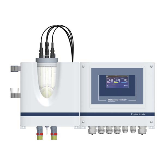
- Page 1 EZETROL TOUCH ® WALLACE & TIERNAN MEASURING, CONTROL AND DOSING SYSTEM Version 2.01 and later INSTRUCTION MANUAL...
- Page 2 Translation of the original instruction. In some countries, DEPOLOX, OSEC, Barrier, Chem-Ad and Wallace & Tiernan are trademarks of Evoqua, its subsidiaries or affiliated companies. No part of this document may be reproduced in any form (printed, photocopy, microfilm, or any other procedure) or saved, processed, copied, or distributed using electronic data systems - without the express prior written con- sent of Evoqua Water Technologies GmbH.
- Page 3 Ezetrol touch Contents Contents Introduction ................5 Target groups ......................5 Structure of the documentation ................5 Conventions......................5 Safety..................6 Intended use......................6 General safety instructions ..................6 Specific operating phases..................7 Warranty conditions....................7 Exclusion of liability ....................7 Description................. 8 General ........................8 Complete system.....................8 Retrofit kits/extensions ...................8 Optional accessories....................8 Electronics module ....................9 Flow cell.........................18...
- Page 4 Ezetrol touch Contents Operation ................52 Display and control elements ................52 “Measurement” menu field.................. 53 “System“ menu ..................... 55 Web visualization....................64 Firmware update ....................65 Calibration......................66 Messages, alarms and errors ................70 Errors and remedies....................73 Maintenance................74 Maintenance intervals ..................
- Page 5 Ezetrol touch 1. Introduction Introduction WARNING Electrocution hazard. Target groups This instruction manual provides the informa- tion required for installation, operating and ATTENTION maintenance personnel for the installation, Environmental hazard! operation and maintenance of the Ezetrol Do not throw away or burn the batteries! touch Measuring, Control and Dosing System.
- Page 6 2. Safety Ezetrol touch Safety State-of-the-art technology The Ezetrol touch has been constructed in accordance with the technological state-of- Intended use the-art and the accepted rules of safety engi- The Ezetrol touch Measuring, Control and neering. However, if the Ezetrol touch is used Dosing System with installed sensors is desig- by persons who have not been adequately ned exclusively for measurement and control...
- Page 7 Ezetrol touch 2. Safety Warranty conditions IT security The manufacturer offers IT security mecha- The following must be observed for compli- nisms for its products to support secure sys- ance with warranty conditions. If any of the tem operation. We recommend checking on a conditions are not met, the warranty is void.
- Page 8 3. Description Ezetrol touch Description As a result of the integrated process manage- ment, the following functions can be realized: General • Measurement of the hygiene parameters and control The Ezetrol touch has a modular structure and • Dosing of disinfectants comprises: •...
- Page 9 Ezetrol touch 3. Description Electronics module Typical applications: • Measurement and control of chlorine, pH and as an option ORP (Redox) or conducti- 3.5.1 Design vity in the swimming pool • Actuation of dosing pumps or chlorine gas metering systems •...
- Page 10 3. Description Ezetrol touch Controller for Type Parameter description Action Dosing Cl Solenoid pump (pulse-fre- 2-point Solenoid pump 2P Correction pH or pH quency controller) Correction conductivity 2 solenoid pumps (pulse- 3-point Solenoid pump 3P Correction pH and pH frequency controllers) Dosing Cl Dosing contact 2-point...
- Page 11 Ezetrol touch 3. Description Analog output controller 2-point If the setpoint is exceeded, the controller out- With a control output of 0%, the output current put switches off immediately (provided that is 0 or 4 mA; with a higher control output, the the minimum duty cycle has elapsed).
- Page 12 3. Description Ezetrol touch Tn - Integral action time (I-element) of the PI Tu – Loop dead time controller Time required between start of dosing and On the basis of the integral action time Tn, clear recognition of an increase in the mea- the dosing rate changes constantly until the sured value.
- Page 13 Ezetrol touch 3. Description 3.5.5 Alarms Acknowledgment “ACK with reset“ • In the event of an alarm, the alarm sym- The electronics module supports up to eight bol and the message symbol flash and the freely configurable alarms. The alarms can be relay is active until acknowledged.
- Page 14 3. Description Ezetrol touch 3.5.6 Auto tune (only applies to free Auto tune must not be started: chlorine) • if a large volume of fresh water is being added The electronics module is equipped with an • if the measuring cell has not been run in Auto tune function to facilitate commissioning •...
- Page 15 Ezetrol touch 3. Description Auto tune sequence Each Auto tune phase is now displayed with a status message: Display text Explanation Initialization Start Control signal Ym = 0 % Chlorinator to 0 % or dosing pump off Wait for act. value X = 20 % Delay until act.
- Page 16 3. Description Ezetrol touch Possible error conditions: 3.5.7 Safety functions • Initial value not reached (display: “T = > 8h") The electronics module is equipped with vari- When Auto tune has started and the ous integrated safety functions to ensure sys- dosing system has closed or the dosing tem safety and minimize the risk of accidents.
- Page 17 Ezetrol touch 3. Description Circulation monitoring • NOTICE DANGER Controller switch-off is only effective in “Safety MAN. mode“. Risk of injury or death! A circulation monitoring device must be Digital input DI 2 to DI 5 installed in the unit and connected to the Various functions can be assigned to the digi- electronics module.
- Page 18 3. Description Ezetrol touch 3.5.9 Relay outputs 3.5.10 Interfaces The electronics module has a maximum of six The interfaces are described in detail in chap- relays, each with a changeover contact. These ter 4. The following interfaces are available: switches are assigned various switching tasks •...
- Page 19 Ezetrol touch 3. Description 3.6.2 Function At this point, a maximum back pressure of 1.5 bar is permitted. The following section describes the functional A sample extraction unit is used to draw sam- principle of the flow cell from the sample ple water from the cell body through the low- water inlet to the sample water outlet.
- Page 20 3. Description Ezetrol touch 3.7.2 pH sensor As the chloride concentration of the electro- lyte remains almost constant, the potential of The pH sensor consists of a pH combination the reference electrode is also constant. Salt electrode. The glass electrode is the most rings as an additional salt depot further powerful sensor for pH measurement, with a increase the service life of the ORP sensor.
- Page 21 Ezetrol touch 3. Description Technical data 3.8.1 Electronics module (module name E02) Dimensions (WxHxD) 12.6“ x 12.2“ x 6“ (320 x 311 x 153 mm) Weight approx. 7.7 lbs (3.5 kg) Housing Protection rating IP66 Mains connection 100 to 240 V AC ± 10%, 50 to 60 Hz, 15 W 4.3”...
- Page 22 3. Description Ezetrol touch NOTICE When connecting inductive or capacitive loads (e.g. pump with integrated switching power supply), an additional power relay with suitable specification must be provided. Each relay output has an integrated 3.15 A fuse as overcurrent protection. Typical use of relays: enable contact for dosing device, control of motors or dosing pumps.
- Page 23 Ezetrol touch 3. Description 3.8.3 Sensors NOTICE When disinfecting with inline electrolysis systems or hydrogen drainage into the pool water, the gold version of the chlorine or ORP (Redox) sensor must be used. Chlorine sensor platinum version (W3T160652) gold version (W3T160991) Amperometric 3-electrode sen- Amperometric 3-electrode sen- sor with platinum electrodes, salt...
- Page 24 3. Description Ezetrol touch pH sensor (W3T169297) combination electrode with universal membrane glass, salt reserve, Version zirconium dioxide diaphragm, polymerized solid electrolyte, Ag/AgCl reference electrode Measurement range pH 0 to 12 (temporarily to pH 14) Working tempera- 23 to 176°F (-5 to +80°C) ture range Operating pressure 6 x 10...
- Page 25 Ezetrol touch 4. Interfaces Interfaces DANGER Risk of injury or death! External voltages may still be connected even if the operating voltage is switched off. USB interface The electronics module is equipped internally with a USB interface. It is used to update the firmware via USB stick (chapter 6.5) or for use as a data logger via USB stick.
- Page 26 4. Interfaces Ezetrol touch The integrated 2-port switch replaces additio- Meaning of the LED: nal external switch assemblies. To avoid long • green lights up: Ethernet connection esta- process times, we recommend that you do not blished daisy-chain more than three devices via the •...
- Page 27 Ezetrol touch 4. Interfaces Web view in the browser: 4.3.3 Network setting under Windows 10 Start the browser, e.g. Firefox or Internet Windows 10 automatically establishes a net- Explorer. work connection as soon as a network card is Enter the IP address of the electronics detected in the PC or laptop computer.
- Page 28 4. Interfaces Ezetrol touch Under the menu “Ethernet properties,” Windows 10 with an alternative configuration select the element “Internet protocol Ver- With Windows 10, it is also possible to set an sion 4 (TCP/Pv4).” Only the element alternative configuration. “Internet protocol Version 4 (TCP/IPv4)" is Carry out steps 1 to 4 as described under required;...
- Page 29 Ezetrol touch 4. Interfaces 4.4.1 Data formats The table below contains the data format used for transmission of the process data: Data type Size (bit) Typical names Value range min. Value range max. INT8 -128 UINT8 INT16 -32.768 32.767 UINT16 65.535 INT32 -2.147.483.648...
- Page 30 4. Interfaces Ezetrol touch Modbus Register Ezetrol touch IP adress of the device, e.g. 192.168.200.11 Port: 502 Modbus Type Access Designation Description Register Byte System information 400001 ASCII System name e.g. "Ezetrol touch" 400011 ASCII Software Version e.g. "V:1.00" 400016 ASCII act.
- Page 31 Ezetrol touch 4. Interfaces Modbus Type Access Designation Description Register Byte (Ch.2) pH - Measurement 400115 FLOAT Measured value 400117 ASCII Measured unit "pH / mg/l" 400122 FLOAT Lower range 400124 FLOAT Upper range 400126 FLOAT Current setpoint in the measuring range 400128 FLOAT Current measuring range/...
- Page 32 4. Interfaces Ezetrol touch Modbus Type Access Designation Description Register Byte Status messages 400300 UINT16 Alarm stats 1 = Alarm pending Alarm 1 Alarm 2 Alarm 3 Alarm 4 Alarm 5 Alarm 6 Alarm 7 Alarm 8 400301 UINT16 Digital inputs 1 = DI active (open) Sample water STOP - DI1 DI 2...
- Page 33 Ezetrol touch 4. Interfaces Modbus Type Access Designation Description Register Byte 400306 400307 UINT16 Operation mode controller Coding see Reg. 400304 4 (Cond.) 400308 400309 400310 UINT32 Error code chlorine (Ch.1) 1 = error active Zero point calibration DPD calibration pH7 calibration pHX calibration Error calibration e.g.
- Page 34 4. Interfaces Ezetrol touch Modbus Type Access Designation Description Register Byte 400314 UINT64 Error code pH (Ch.2) Coding see Reg. 400310 400318 UINT64 Error code ORP (Redox) (Ch.3) Coding see Reg. 400310 400322 UINT64 Error code conductivity (Ch.4) Coding see Reg. 400310 400326 UINT64 Error code temperature (Ch.5) Coding see Reg.
- Page 35 Ezetrol touch 4. Interfaces Modbus Type Access Designation Description Register Byte (Ch.1) Chlorine - Controller parameter 401000 FLOAT Setpoint (W) in the measuring range 401002 FLOAT P-element(Xp) 0 - 1000% 401004 FLOAT I-element (Tn) 0.0 - 100.0 min 0 = Tn inactive (Ch.2) pH - Controller parameter 401006 FLOAT...
- Page 36 4. Interfaces Ezetrol touch Modbus Type Access Designation Description Register Byte (Ch.4) Reserved 401086 FLOAT Min. value 1 Lower range - Max 1 401088 FLOAT Max. value 1 Min 1 - Upper range 401090 FLOAT Hysteresis value 1 1 - 25 Digit 401092 FLOAT Min.
- Page 37 Ezetrol touch 5. Installation Installation Required ambient conditions NOTICE Scope of delivery Correct and safe operation can only be gua- The scope of delivery includes the following, ranteed if the requirements for the ambient conditions are met. All applicable national depending on the version selected: and local regulations must be observed! •...
- Page 38 5. Installation Ezetrol touch Installation of the module NOTICE Install the electronics module and flow cell • The electronics module is not suitable with or without DIN rail. Dimension drawing for electrical connection with perman- chapter 5.5.3. ently installed cable conduits. If the cable glands do not meet local installa- 5.5.1 With DIN rail tion rules and regulations, these glands...
- Page 39 Ezetrol touch 5. Installation 5.5.3 Dimension drawing...
- Page 40 5. Installation Ezetrol touch Removing and fitting the Installing the optional strainer housing cover Release the screw joint on the sample water inlet with ball valve (A) (threaded 5.6.1 Flow cell connection G 1/2” A). Connect strainer with pipe clamp (B). Removing Connect sample water inlet (C).
- Page 41 Ezetrol touch 5. Installation • To prevent long loop dead times, ensure that the lines in the sample water inlet are as short as possible and do not have a large line cross-section. Long measuring dead times mean poorer control quality! •...
- Page 42 5. Installation Ezetrol touch 5.10 Sample water extraction options Example for sample water extraction using a booster pump...
- Page 43 Ezetrol touch 5. Installation Example for sample water extraction - Part list on page 44...
- Page 44 5. Installation Ezetrol touch 5.11 Inserting or replacing electro- Beispiel: Sample water extraction, drawing on page 43 de cleaning sand • for fresh water (Part no. W3T158528) The electrode cleaning sand (part no. • for salt water (Part no. W3T158529) W3T171317) is supplied in a plastic bottle, the Item Qty.
- Page 45 Ezetrol touch 5. Installation 5.12 Installing and connecting sen- sors, LED glow stick and multi- sensor NOTICE The sensors must be prepared accordingly. Keep the watering cap of the chlorine sen- sor and the transport container of the pH and ORP sensors in a safe place for later use. Please follow the relevant operating instruc- tions for the sensors! Fig.
- Page 46 5. Installation Ezetrol touch 5.13 Installing calibration aids 5.14 Electrical installation Two calibration clips are installed in the hou- DANGER sing cover. They are pushed into the side of Risk of injury or death! the basic housing at the back. The clip with the External voltages may still be connected plastic insert for the sensor is pushed into the even if the operating voltage is switched off.
- Page 47 Ezetrol touch 5. Installation Open the housing cover of the electronics NOTICE module. • The electronics module is not suitable Connect the power supply in accordance for electrical connection with perman- with the wiring diagram (chapter 9.). ently installed cable conduits. NOTICE •...
- Page 48 5. Installation Ezetrol touch 5.15 Startup • The electronics module is wired in accor- dance with the wiring diagram (circuit dia- DANGER gram) and local regulations. • Ensure that all transport protection was Risk of injury or death! removed. The Ezetrol touch must not be operated with •...
- Page 49 Ezetrol touch 5. Installation 5.16 Installing retrofit kits/extensions ORP (Redox) measurement (if available) • Check the limit values 1 and 2 for ORP DANGER (“Min" and “Max"), adjust if neces- sary. Risk of injury or death! • Check the measurement range for External voltages may still be connected even if the operating voltage is switched off.
- Page 50 5. Installation Ezetrol touch 5.16.2 ORP sensor measuring module 5.16.3 Conductivity sensor measuring module Disconnect the electronics module from the power supply. Disconnect the electronics module from Remove the housing cover of the electro- the power supply. nics module. Remove the housing cover of the electro- Feed the ORP (Redox) sensor cable nics module.
- Page 51 Ezetrol touch 5. Installation 5.17 Shut-down DANGER Risk of injury or death! External voltages may still be connected even if the operating voltage is switched off. Disconnect the electronics module from the power supply. Drain the sample water supply line and drainage line.
- Page 52 6. Operation Ezetrol touch Operation Main scruture From the main menu, you can call up the sys- tem settings, the measured values menus and Display and control elements the controller menus. To access the correspon- The colored graphic display with capacitive ding menus, tap the Measurement menu touchscreen is the display and control ele- fields or tap the...
- Page 53 Ezetrol touch 6. Operation “Measurement” menu field Symbols Meaning This menu shows the current measured value Message/error active and the sensor signal. All settings relating to Tap the symbol to open the mes- measurements, such as range, limit values, sage window. controller settings and calibration must be •...
- Page 54 6. Operation Ezetrol touch Chlorine measurement parameters Min: within range Measurement Hysteresis: 0.01 to 0.25 Range: 1, 2, 3, 5 and 10 mg/l Limits value II Unit: mg/l, ppm Max: within range Measurement filter: off/low/middle/strong Min: within range Limits Hysteresis: 0.01 to 0.25 Limits value I Controller Max: within range...
- Page 55 Ezetrol touch 6. Operation Conductivity measurement parameters Temperature measurement parameters Measurement Measurement Upper range : 5.00/10.0/20.0/50.0/100.0/ Measurement filter 200.0/300.0 mS/cm Limits 500/1000/2500 µS/cm Limits value I Unit: mS/cm, µS/cm Max: 0 to 50 °C Measurement filter: off/low/middle/strong Min: 0 to 50 °C Additional display: off/NaCl [g/l]/TDS Hysteresis: 0.1 to 2.5 °C TDS Factor: 0.40 to 1.00...
- Page 56 6. Operation Ezetrol touch 6.3.1 “Operation mode” menu Depending on the desired measurement, the corresponding calibration menus can be selec- Select in this menu the operation mode. ted. The menu can be opened in via the Sys- Call up the Home menu. tem menu or via the Measurement menu symbole field.
- Page 57 Ezetrol touch 6. Operation Tap the symbol. Conductivity Date of last calibration: Date and time Calibration history (press „Date of last calibration“) Calibration: 60 mS/cm or 600 µS/cm Calibration with the calibration solution or or comparative measurements Temp. Offset: Temperature calibration of Press ”+”...
- Page 58 6. Operation Ezetrol touch Press the “Calibrate” button to open the mA outputs 1/2/3/4 input menu. mA outputs: off, 0 to 20 mA, 4 to 20 mA Measurement: Chlorine, pH, ORP (Redox), conductivity, temperature Signal: Measured value, Yout Explanation of digital input settings: •...
- Page 59 Ezetrol touch 6. Operation 6.3.4 ”Alarm configuration” menu Alarm 1/2/3/4 Alarms 1 to 8 are configured in the “Alarm Acknowledge: Configuration” menu. The Ezetrol Touch Input specifies whether an alarm is defi- offers the option of setting various alarm con- ned as an alarm without acknowled- figurations.
- Page 60 6. Operation Ezetrol touch 6.3.6 ”Settings” menu Hold Function: On/Off The device settings not relating to measured The hold function is used to either buf- values are configured in the Settings menu. fer all measured values or keep them constant during calibration. This pre- Call up the HOME menu.
- Page 61 Ezetrol touch 6. Operation Max. dosing time: 00:00 to 10:00 h Unlock pattern: The maximum dosing time determines Menu for entry/definition of a Level 3 the length of time in which all control unlock pattern. The entry must be outputs must reach their setpoint in the repeated as confirmation.
- Page 62 6. Operation Ezetrol touch DHCP: On/Off Reset user administration: In the setting “DHCP = On,” the network configuration is automatically defined Reset dosing average: by the DHCP server and cannot be confi- gured manually. The network settings are displayed. In the setting “DHCP = Off,” the network NOTICE settings must be configured manually.
- Page 63 Ezetrol touch 6. Operation User symbol yellow = Level 2 Set the parameter “Access control” to • User logged in on Level 2. “On.” • Read rights for all settings, sensor calibrat- To define or change a password or locking ion, change of operation mode, change code, the password “3000”...
- Page 64 6. Operation Ezetrol touch To enter a password Padlock symbol red, closed Press the parameter “Password.” • User logged out Enter the desired password via the input • Read rights only keypad. Padlock symbol black, open Confirm with the Enter key. •...
- Page 65 Serial number: NOTICE Display device serial number A firmware update can be downloaded free IP configuration of charge from the homepage of Evoqua IP: Enter a fixed IP address Water Technologies GmbH. (contact the network administrator) Network mask: DANGER...
- Page 66 6. Operation Ezetrol touch Calibration Using an insulated screwdriver, briefly press the Update button (B) on the When calibrating the measurements, variati- motherboard. ons in the calibration solutions, buffer soluti- NOTICE ons or comparative measurements are adjusted. Calibration is performed for new The update takes approximately 1 to 2 minu- devices (first commissioning) and to recali- tes.
- Page 67 Ezetrol touch 6. Operation Checking the zero point calibration: 15 Press the “Calibration” button. An input field opens. Open the menu ”Calibration” – ”Chlorine”. 16 Use the input keys to enter the determi- Close the ball valve on the sample water ned value.
- Page 68 6. Operation Ezetrol touch pH X-span alignment 6.6.3 ORP calibration (Redox) NOTICE NOTICE If buffer solutions other than those stated ORP (Redox) sensors have long running-in are used, the pH value of the buffer solution times. This means that after calibration with must be lower than pH 6 or higher than pH calibration solution, it can take several hours for the measured value to stabilize.
- Page 69 Ezetrol touch 6. Operation 6.6.4 Conductivity calibration 11 Press "Enter" to save the entry. 12 Remove the conductivity sensor from the NOTICE top clip. • Conductivity sensors have no running-in 13 Screw the conductivity sensor into the cell time. body cover and tighten the clamp connec- •...
- Page 70 6. Operation Ezetrol touch Messages, alarms and errors Messages, alarms and errors are displayed on the electronics module with the colored mes- sage symbol. Error messages can occur that can be acknowledged or that can not be acknowled- ged. If several messages occur at the same time, the number of messages appears next to the symbol.
- Page 71 Ezetrol touch 6. Operation Error message Cause Remedy Slope error The current difference required Check chlorine sensor. for span alignment over the entire Clean electrodes. measurement range was less than Check the pH value of the water the minimum value. Range: Mini- (<...
- Page 72 6. Operation Ezetrol touch Error message Cause Remedy Chlorine sensor: Chlorine sensor Screw in sensor correctly. not screwed in. No sand cleaning. Check sand cleaning. Sensor, sensor cable or sensor Check the sensor, sensor cable or measuring module defective. sensor measuring module, replace Sensor measuring module µA if necessary.
- Page 73 Ezetrol touch 6. Operation Errors and remedies NOTICE The table below shows and explains possible faults. If it is not possible to remedy the fault or error yourself, please contact your affiliate. Error message Cause Remedy No power supply. Turn external switch or fuse on. Check the power supply and No indication on device Device fuse defective.
- Page 74 7. Maintenance Ezetrol touch Maintenance Maintenance parts set DANGER Part no. Designation Risk of injury or death! Maintenance parts kit, External voltages may still be connected W3T158874 annual maintenance even if the operating voltage is switched off. Maintenance parts kit, 4 W3T158878 years NOTICE...
- Page 75 Ezetrol touch 7. Maintenance Cleaning the flow rate monitor and check valve Switch off the power supply. Drain the sample water supply line and drainage line. Remove the housing cover of the flow cell. Remove the filter unit. To do this, release both knurled nuts.
- Page 76 7. Maintenance Ezetrol touch 7.7 Replacing the fuses on the CPU 7.8 Replacing the battery board WARNING WARNING Risk of injury or damage to the device! Only authorized and qualified electricians Risk of injury or damage to the device! are permitted to install the Ezetrol touch Only authorized and qualified electricians and open the housing.
- Page 77 Ezetrol touch 8. Spare parts, Accessories and Retrofit kits Spare parts, Accessories and Retrofit kits NOTICE For reasons of safety, only use original spare parts. Please contact our customer service if you need any spare parts. Electronics module (module name E02) Part No.
- Page 78 8. Spare parts, Accessories and Retrofit kits Ezetrol touch Flow cell (module name D02)
- Page 79 Ezetrol touch 8. Spare parts, Accessories and Retrofit kits Item Part No. Designation Item Part No. Designation W3T247776 Basic housing W3T161450 Plug W2T507548 Type plate W3T168859 O-ring W3T247777 Housing cover W3T172861 O-ring W3T166170 Shut-off valve W2T863568 Adapter W2T507615 Flat nut W3T438413 Hose W3T158559...
- Page 80 8. Spare parts, Accessories and Retrofit kits Ezetrol touch Sensors and extension cables NOTICE When disinfecting with inline electrolysis systems or hydrogen drainage into the pool water, the gold version of the chlorine or ORP (Redox) sensor must be used. Chlorine ORP (Redox) Conductivity...
- Page 81 Ezetrol touch 8. Spare parts, Accessories and Retrofit kits Accessories Part-Nr. Designation W3T165563 Impedance converter for pH or ORP sensor W3T158721 Strainer with ball valve, straight W3T389201 Set of fittings for strainer Metric PVC tubing, fabric-reinforced ø 4 x 3 ø...
- Page 82 9. Wiring diagram Ezetrol touch Wiring diagram WAE9686 - Issue 07-1119...
- Page 83 Ezetrol touch 9. Wiring diagram...
- Page 84 9. Wiring diagram Ezetrol touch...
- Page 85 Ezetrol touch 9. Wiring diagram...
- Page 86 10. EC Declaration of Conformity and Certificate Ezetrol touch 10. EC Declaration of Conformity and Certificate...
- Page 87 Ezetrol touch 10. EC Declaration of Conformity and Certificate...
- Page 88 70138021 2017-07-14 Project: Date Issued: Issued to: Evoqua Water Technologies GmbH Auf der Weide 10 Gunzburg, 89312 GERMANY The products listed below are eligible to bear the CSA Mark shown with adjacent indicators 'C' and 'US' for Canada and US or with adjacent indicator 'US' for US only or without either indicator for Canada only.
- Page 89 Ezetrol touch NOTES...
- Page 90 Ezetrol touch NOTES...
- Page 91 Ezetrol touch Wallace & Tiernan® Products worldwide Australia Canada China +61 1300 661 809 +1 905 944 2800 +86 21 5118 3777 info.au@evoqua.com wtoe.can@evoqua.com sales.cn@evoqua.com France Germany Singapore +33 1 41 15 92 20 +49 8221 9040 +65 6559 2600 wtfra@evoqua.com...
- Page 92 © 2021 Evoqua Water Technologies GmbH Subject to modifications WT.050.500.200.DE.IM.0121 W3T401145 Issue 09-0121 Auf der Weide 10, 89312 Günzburg, Germany +49 (8221) 904-0 www.evoqua.com...
Need help?
Do you have a question about the WALLACE & TIERNAN EZETROL TOUCH and is the answer not in the manual?
Questions and answers