Advertisement
Quick Links
SPX Corporation
5885 11th Street
Rockford, IL 61109-3699 USA
Internet Address:
http://www.powerteam.com
Tech. Services: (800) 477-8326
Fax: (800) 765-8326
Order Entry: (800) 541-1418
Fax: (800) 288-7031
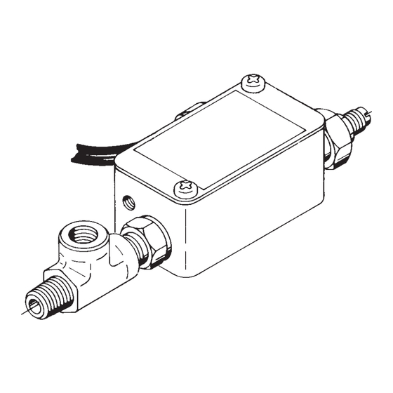
The #9625 Pressure Switch can be mounted directly to a control valve manifold or can be mounted in-line. The switch
is designed to stop the pump motor or electrical device at a pressure setting and to restart the motor when pressure
falls below that setting.
WARNING
: To help prevent personal injury,
● ●
All electrical work must be done by a qualified electrician.
● ●
Disconnect the power supply before removing the electrical box cover.
Pump Mounted Installation
Mount the pressure switch to the control valve or the manifold by threading the switch fitting into the port provided for
a pressure gauge. An elbow can be used to change the angle (see Figure 1), and a tee fitting (supplied) can be used
if both a pressure switch and a gauge are required (see Figure 2).
IMPORTANT: Seal all external pipe connections with a high-quality, nonhardening thread sealant, such as
Power Team HTS6. Teflon tape can be used to seal hydraulic connections if only one layer of tape is used.
Apply the tape carefully, two threads back, to prevent it from being pinched by the coupler and broken off
inside the system. Any loose pieces of tape could travel through the system and obstruct the flow of oil or
cause jamming of precision-fit parts.
© SPX Corporation
®
®
SPX Corporation
655 Eisenhower Drive
Owatonna, MN 55060-0995 USA
Phone: (507) 455-7000
Tech. Services: (800) 533-6127
Fax: (800) 955-8329
Order Entry: (507) 455-1480
Fax: (800) 283-8665
International Sales: (507) 455-7223
Fax: (507) 455-7746
PRESSURE SWITCH
Pressure Range: 1,000 - 10,000 PSI
Contact Rating Max.: 5 AMPS at 250 VAC
INSTALLATION
Form No. 102507
Operating Instructions
for:
Note: Shaded
areas reflect last
revision(s) made to
this form.
Sheet No.
Issue Date:
9625
1 of 2
Rev. 1-15-95
Advertisement

Summary of Contents for SPX POWER TEAM OTC 9625
- Page 1 Form No. 102507 ® ® SPX Corporation Operating Instructions 655 Eisenhower Drive SPX Corporation Owatonna, MN 55060-0995 USA for: 5885 11th Street Phone: (507) 455-7000 Rockford, IL 61109-3699 USA Tech. Services: (800) 533-6127 Internet Address: http://www.powerteam.com Fax: (800) 955-8329 Tech. Services: (800) 477-8326 Order Entry: (507) 455-1480 9625 Fax: (800) 765-8326...
- Page 2 Operating Instructions, Form No. 102507, Back sheet 1 of 2 In-Line Installation The pressure swtich can be mounted "in-line" between the hydraulic pump and cylinders as shown in Figure 3. FIGURE 3 Electrical Sequence and Operation WARNING: To help avoid personal injury, all electrical work must be done by a qualified electrician. North American &...
- Page 3 Operating Instructions Form No. 102507 Adjusting the Pressure Regulating Valve NOTES: ● ● Adjust the pressure regulating valve by increasing it to a preferred pressure setting. Do not adjust it by decreasing from a higher to a lower pressure. ● ● Range of pressure settings is from 1,000 minimum to 10,000 PSI maximum--depending upon the PSI range set for each pump model.
- Page 4 Operating Instructions, Form No. 102507, Back sheet 2 of 2 Adjusting the Pressure Switch Electrical Switch WARNING : Disconnect the power supply before removing the electrical box cover. The microswitch located inside the electrical switch can be adjusted if necessary. 1.
Need help?
Do you have a question about the OTC 9625 and is the answer not in the manual?
Questions and answers