Advertisement
Quick Links
Advertisement

Summary of Contents for Humboldt Redwood H-4114.MCU
- Page 1 07.24 H-4114.MCU EDG Calibration Module...
- Page 2 this is a blank page corrector...
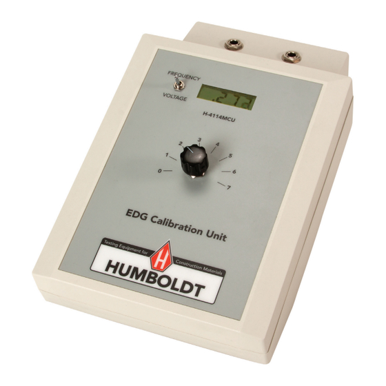
- Page 3 EDG Calibration Procedure For SD Model Set the toggle switch of the Calibration unit to Frequency, rotary switch to "0" position. Connect the soil sensor to the EDG and power on. Allow to warm up for at least 5 minutes. Insert soil sensor into the calibration unit with the label in the back, Make sure the brass terminals on the sensor make contact with the spring terminals on the calibration unit.
- Page 4 After entering frequency on the EDG, switch the toggle switch on the calibration unit to "voltage" On the EDG, press the "Setup" icon (bottom left) and scroll down and click on "Engineering" 10. Enter password 2-2-2-3-4. 11. In the main "Engineering" screen Click on "A/D Converter". 12.
- Page 5 13. Switch the rotary switch to "1" wait a few seconds for the reading on the calibra- tion unit to stabilize and click on "Refresh" on the EDG. 14. Repeat for the remaining rotary switch positions, until the table is complete. 15.
- Page 6 23. Return to the main Engineering screen on the EDG. Insert the USB flash drive into EDG and click Import Cal. 24. Click on the calibration file and click Select. Wait for the prompt that the import was successful. 25. Remove the soil sensor from the calibration unit and connect the Calibration Check Box to the sensor.
- Page 7 EDG Calibration Procedure For C Model Note: Before you begin: Your test area should be as far from other powered electronic equipment as possible. Do not use florescent lights and compact florescent lights (CFL) on the test area surface (overhead lights ok). (ii) When taking measurements, do not touch the sensor wires or connector.
- Page 8 NOTE: Never have a powered soil sensor plugged into an unpowered calibration unit. 5. Run EDG Calibration Software on the PC. Ensure the calibration software is the most up to date version (check our website). 6. If you do not see the screen "EOG Calibration Wizard", you are in advance mode: click on the Wizard View icon.
- Page 9 Enter the serial number click OK the following screen will display, Select Edit Calibration...
- Page 10 Enter the Factory Mode on the EDG EDG Main Job Sites Soil Models Data Sharing View Information *Setup use the down arrow key to position the curser at the setup Press the EDG key four time and then press SEL the following menu will be displayed EDG Setup Set Date/Time...
- Page 11 10. From the above menu, navigate down to the “Read A/D Converter – Re- lays are "OFF" and press "SEL" the following menu will be displayed Soil Values, Relays OFF R=4528.76 C=109.22(cap. offset not included) Z=446.20 Cap. Offset for relays off=0.000 11.
- Page 12 16. Record Unadjusted Phase value 17. Repeat steps 9-15 for all 8 rotary positions on the Calibration Unit. After obtain ing each set ofreading, press the EXIT button on the EDG. Then move the rotary switch on the Calibration Unit to the next position, wait a few seconds for the reading to stabilize, then press SEL again.
- Page 13 Also ensure the R2 values are green, not red. If red, the calibration is not correct. You can click on the tabs for volts, cunent & phase to view the plots and try to locate the erroneous data (bad data will be far from the fit line).
- Page 14 Offsets". 25. Navigate back to "A/D Converter Functions" 26. Attach the black calibration box to the Soil Sensor and press "SEL". Soil Values, Relays OFF R=933.31 C=63.15 (cap. Offset not included) Z=596.44 Cap. Offset for relays off = 0.000 27. Record the Z value for the Calibration Box. It is recommended you exit and read the Z values a few times and take an average.
-
Page 16: Construction Materials
Warranty Humboldt Mfg. Co. warrants its products to be free from defects in material or workmanship. The exclusive remedy for this warranty is Humboldt Mfg. Co., factory replacement of any part or parts of such product, for the warranty of this product please refer to Humboldt Mfg. Co. catalog on Terms and Conditions of Sale.
Need help?
Do you have a question about the H-4114.MCU and is the answer not in the manual?
Questions and answers