
Related Manuals for Richmond FSR106

Summary of Contents for Richmond FSR106
- Page 1 Specification Manual FSR106 Full Electric Stacker Note: Please read this manual before using! Note: Please do not use it before completing the installation!
-
Page 2: Table Of Contents
Contents Chapter 1 Foreword Chapter 2 Specifications Chapter 3 Description of the machine Chapter 4 Safety regulations Chapter 5 Use of the machine Chapter 6 Battery Chapter 7 Maintenance Chapter 8 Hydraulic diagram Chapter 9 Electrical diagram Chapter 10 Trouble shooting... -
Page 3: Chapter 1 Foreword
Chapter 1 Foreword This manual contains all the instructions for the use of the machine and the necessary knowledge for its correct use. Read this manual carefully before the machine is taken into use to avoid errors. Correct operations and regular inspections are factors of vital importance for the operating economy and lifetime of the machine. -
Page 4: Chapter 2 Specifications
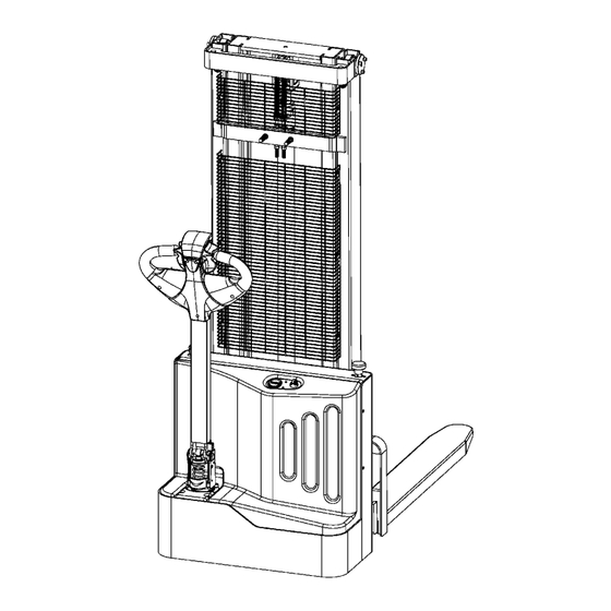
Chapter 2 - Specifications Technical specifications and major dimensions are shown in TABLE 1 and FIGURE 1, Respectively. FIGURE 1... - Page 5 TABLE 1 Model Unit FSR106 Load Capacity Q (kg) 1300 Load center C (mm) Max. height of forks H1 H1(mm) 3000 Max. height of machine H2 H2 (mm) 3540 Fork length L1 L1(mm) 1150 Overall fork width W1 W1(mm) Fork size...
-
Page 6: Chapter 3 - Description Of The Machine
Chapter 3 - Description of the machine This machine is an electric forklift truck with tiller bar drive and is perfect loads on for storing and transporting perfectly even surfaces. The controls are easy to see and use. The drawing shows its main specifications. FIGURE 2 10)Driving Wheel 1)Frame... -
Page 7: Chapter 4 Safety Regulations
Chapter 4 Safety Regulations Safety Device A) Emergency Stop Switch (No.16/ Figure 2) B) Brake (No.10/ Figure 2) C) Handle Angle interlock switch(No.9/ Figure 2) D) Height Limit Switch (No.8/ Figure 2) E) Flow-limiting Valve (No.11/ Figure 2) F) Pressure-limiting Valve (No.11/ Figure 2) G) Emergency (No.5/ Figure 2) H) Protective Net(No.4/ Figure 2)... - Page 8 driver must ensure that the load is evenly placed on the forks and in perfect order. Uneven loading not only damages stacker but also causes upsetting. 11) It is forbidden to move the truck with the forks in their upper position. The forks must not be lifted more than maximum 300mm when driving.
-
Page 9: Chapter 6 Use Of The Machine
Chapter 6 Use of the machine Set up Before starting the machine check that all the parts are in perfect condition, check the performance of all the units and the safety devices. Move the truck with battery current and never with rectified alternating current so as not to damage the electrical components. - Page 10 Movement Before moving the truck check that the horn and the brake work and that the battery is completely charged. Turn the key to the ON position and move the tiller bar to its movement position. Turn the governor slowly and move towards the relative work area.
- Page 11 capacity relative to the height indicated on the appropriate plate. WARNING: When the load is lifted steering and braking man-oeuvres must be carried out slowly and very carefully. Transport...
-
Page 12: Chapter 6 Battery
Chapter 6 Battery Inspection, charging and substitution of the battery must be carried out by authorized personnel follow the manufacturer’s instructions. It is forbidden to smoke or keep inflammable or spark-producing material near the truck or the battery charger. The area must be kept well aired. The caps of the elements must be kept dry and clean. -
Page 13: Maintenance Table
3) Never expose the battery to naked flames. Fires may occur from the formation of explosive gas 4) Never make temporary or incorrect electrical connections 5) Terminal points must be well tightened and free of scale. Cable insulation must be in good condition 6) Keep the battery clean, dry and free dust using an antistatic cloth 7) Never place tools or other metal objects on the battery 8) During recharging, check the temperature of the electrolyte, which must... -
Page 14: Hydraulic System
Check return to vertical position ▲ Check wear of remote control switch ▲ Check connections and cable ▲ Check master switch ▲ ELECTRICAL SYSTEM Check horn ▲ Check dead man’s button ▲ Check fuse values ▲ Check performance ▲ Check oil level ▲... -
Page 15: Hydraulic Diagram
Chapter 8 Hydraulic diagram FIGURE8 HYDRAULIC SYSTEM HYDRAULIC ELEMENTS TABLE Item Type Description Lifting cylinder Hose Magnet change valve Check valve Pressure-limiting valve Keep speed valve Motor pump Pump Oil filter Oil tank... -
Page 16: Electrical Diagram
Chapter 9 Electrical diagram... -
Page 17: Troubleshooting
Chapter 10 Troubleshooting The machine doesn’t start BATTERY FLAT CHARGE BATTERY REPLACE MOTOR BRUSHES WORN REPLACE POWER FUSE BLOWN REPLACE SECONDARY FUSE BLOWN REPLACE KEY BROKEN MOUNT NEW KEY CHECK ELECTRICAL SYSTEM... - Page 18 The carriage won’t rise CHECK CONNECTIONS OVERLOADING REDUCE LOAD BATTERY FLAT CHARGE BATTERY NO OIL IN THE TANK ADD OIL...
Need help?
Do you have a question about the FSR106 and is the answer not in the manual?
Questions and answers