Advertisement
Quick Links
Advertisement

Summary of Contents for boostech Masterunit V3
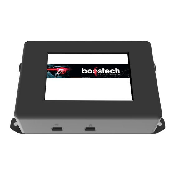
- Page 1 Instruction manual Masterunit V3...
- Page 2 Inhaltsverzeichnis General safety instructions ........................... 4 Introduction ................................6 Interface description ............................... 6 Electrical characteristics ............................8 Dimensions and mounting ............................ 9 Commissioning ............................... 9 Wiring ..................................9 7.1. C-Line cabling ............................... 10 7.2. L-Line wiring ..............................10 7.3. Peripheral wiring ............................15 7.4.
- Page 3 Supply board for use with a car battery ....................35 10.6. Wiring ................................. 35 10.7. Chargers ..............................35 10.8. 10.9. Victron ................................ 35 reassign L-Line board address ........................36 conversion from BMS V2 to BMS V3 ......................39 problem solving ..............................40 Comments and notes ............................
- Page 4 1. General safety instructions Check the delivery contents for completeness and accuracy! Please read the installation and commissioning instructions before installation and follow the instructions described! The listed safety instructions must be observed! All activities described below may only be carried out by electrically trained professionals! A single Li-cell or the interconnected battery pack is inherently operational under voltage (DC) due to its design.
- Page 5 When using or installing components improperly, we do not assume any warranty or liability! Our products and BMS components are generally excluded from extended product liability! This installation manual includes the BMS description, installation instructions, and datasheet of the used cell type (Slave Board)! Please check for any updates to the operating instructions on our website! We do not accept liability for technical or printing errors and their consequences! The information in the descriptions is regularly reviewed.
- Page 6 2. Introduction In almost all electronic devices today, energy storage systems are integrated. These allow storing energy for later use. The amount of energy determines how the energy storage system should be managed. BMS V3 is responsible for managing these energy storage systems, which can have various capacities. These are required, for example, in electromobility or in combination with photovoltaic systems.
- Page 7 Port Plug type Function Number Port 1 2 Pin clamps Main Power Supply: The BMS requires a constant 12V voltage source. The polarity is indicated by a + and a – on the housing. (When looking at the side with the terminal, Vdd (12V) is on the left and Vss (GND) is on the right.) Port 2 4 Pin terminal...
- Page 8 4. Electrical characteristics The BMS requires a constant 12V power supply. The required current depends on the connected devices. You can calculate the current for your system using the following list. Device Current in mA BMS V3 C-Line Current sensor L-Line Current sensor L-Line Cell board 1S L-Line Cell board 3S...
- Page 9 5. Dimensions and mounting The BMS V3 has external dimensions of 145mm x 85mm x 34.5mm. The rear side consists of an aluminum cooling plate, which should be accessible to air or mounted on a thermally conductive surface. The housing comes standard with four mounting tabs positioned at the corners of the housing.
- Page 10 7.1. C-Line cabling All components in the C-Line use standard LAN cables with RJ45 connectors to connect to each other. All C-Line components can be connected using the same bus. It is recommended to connect all components together in series. For this reason, each C-Line component has two RJ45 sockets. Each socket can be used either as an input or an output to connect to the next component.
- Page 11 Figure 2 Four batteries in series with circuit board wiring Figure 3 Four parallel batteries with circuit board wiring To integrate a current sensor, the sensor can be installed in both the positive and ground (GND) paths. For a hassle-free integration, the sensor should be installed in the direction of current flow. For this purpose, there is an arrow on the housing.
- Page 12 Figure 4 Integration eines C-Line Stromsensor The wiring between the slave units is identical for all types in the C-Line. In the last participant of the bus system, which has a free socket, the termination resistor is plugged in. 7.2. L-Line wiring You can find a video for an introduction to our L-Line system with BMS V3 under the following link: https://youtu.be/QELw-PU8vo8...
- Page 13 cable for this is a 10-core flat ribbon cable available on our website (320100). On this cable, sockets (320105) can be crimped at any interval. To achieve optimal crimping results and to avoid bending the contacts inside the socket, we offer a crimping template (320108). For crimping, a parallel-guided tool such as a "Knipex pliers wrench 86 05 250"...
- Page 14 Figure 6 Example of cabling for the L-Line slave units Other L-Line components, such as the L-Line current sensors (310217|310219|310221) or the L-Line relays (310405), can also be connected via the flat ribbon cable. To connect the flat ribbon cable to the BMS V3, an adapter is required.
- Page 15 7.3. Peripheral wiring All peripheral devices are connected via Port 5. This allows the connection of an Energy Storage System (ESS) with a Victron system or the control of a charger. Since the peripheral devices use different connections for their data transmission, each device requires an adapter to be connected. These adapters are available for all our compatible devices in our online shop.
- Page 16 7.4. C-Line/L-Line mixed wiring Within a system, it is not necessary to use only C-Line or only L-Line components. Various combinations are possible. However, both cannot be used within cell communication. This means that only either C-Line slave units or L-Line slave units can be used. For the current sensor, on the other hand, either a C-Line or an L-Line sensor can be installed regardless of the slave units.
- Page 17 7.5.1. Electromobility car/boat with C-Line circuit boards Figure 9 Electromobility application example In Figure 9, a setup used in electromobility is illustrated. Batteries are used to drive an electric motor and its control. In this example, C-Line boards are installed on the battery, and a C-Line current sensor is used to monitor the current.
- Page 18 Important Note: If you do not install a 12V battery, there is a hight probability of interferences on the 12V rail. A 12V battery also acts as a buffer for fluctuations in power consumption on the 12V rail, which a 12V power supply unit can compensate for very poorly.
- Page 19 8. Functions and settings The BMS has several settings that you must select for safe operation. This information is provided by the manufacturers of the batteries and peripheral suppliers you are using. Below, all the information displayed on the screen will be explained, and the functions that can be configured will be described. The BMS is divided into two main parts.
- Page 20 the state of charge, so it is essential to know and enter the usable capacity in Ah of your battery in the BMS! Click here for the service display. It provides additional information on the main page, which can also be viewed quickly. If you have installed your BMS in a vehicle and determined the distance you can travel on a single battery charge during a test drive, you can enter the distance traveled into the BMS.
- Page 21 Next to each setting option, there is always a blue "i" icon, which provides information about the setting when clicked. This way, the display explains itself. It is recommended to go through all the settings and read about what can be configured after the initial setup. Many questions can be answered this way. The individual pages/menu items are navigated using the red arrows at the bottom of the display.
- Page 22 8.2. System settings Main menu -> System settings Canbus Baudrate This baud rate sets the speed of the peripheral bus. For example, the correct baud rate for a Victron system or an ICharger can be configured here. Maximum range The kilometers shown here are purely based on the battery charge level. They do not account for your driving style.
- Page 23 8.3. Battery settings Main menu -> Battery settings Usable battery The usable capacity refers to the amount of energy you intend to extract from your capacity battery. If you have specified the exact cutoff voltages for minimum voltage and shunt voltage that correspond to the battery's limits, then you are using the entire battery capacity.
- Page 24 Caution: If you parallel two or more cells directly and use only one slave unit (not recommended), the BMS considers this as one cell. In this case, you do not need to adjust the voltage divider. The default configuration assumes a single string, so you should enter "1"...
- Page 25 Main menu -> Battery settings -> Advanced settings *(PW protected) Battery Chemistry Here you can select the chemical composition of your battery. The different compositions are grouped into categories based on their similar behavior. Battery Board With this setting, you choose the type of slave units. The C-Line boards are represented by selecting CAN slave boards.
- Page 26 With the add-ons, you can unlock additional features for the BMS. To activate them, you need to purchase the corresponding add-on on the online shop at boostech.de, specifying the BMS serial number. Once purchased, it will be unlocked on your system, requiring the BMS to have an internet connection. In the BMS itself, you can view the unlocked add-ons under System Info in the Extensions field.
- Page 27 Inverters Chargeable The Inverter Add-On allows control of one of the supported inverters. Customer Chargeable he customer interface enables the BMS to output all relevant interface information via CAN or UART. Both protocols can be found on our website as well. 8.4.2.
- Page 28 8.5. Addressing Addressing is responsible for the automatic detection and programming of the batteries. During addressing, each cell with its slave unit is assigned an individual address. For this assignment, NONE of the slave boards must be connected to the BMS during auto-addressing! This is particularly important for C-Line boards, as they do not include address reset functionality.
- Page 29 Procedure Addressing C-Line boards: 1. Verify that all slave units are completely disconnected from the ribbon cable. 2. Start the auto-addressing process in the BMS by clicking on "Scan". Once the message "Addressing begins" appears, proceed to step three. 3. Insert the termination resistor into one of the sockets on the board you want to address first. Then, connect the board to the BMS using a standard LAN cable.
- Page 30 8.6. System Info Under System Info, you will find information about your current BMS. Here, you can check the hardware revision and your serial number. The Extensions window displays the add-ons that are activated on this system. Next to the label 'Software Version', you can find the main software installed on your BMS. Please have all information from this page ready when making a call for support regarding any issues or questions about your BMS.
- Page 31 8.7. Display settings Language Currently, the BMS can display two languages: German and English. Additional languages will be added later. Brightness You can adjust the brightness of the display between 10% and 100% using the sliders. Display If you feel that the triggered functions do not correspond to what you touched on the calibration display, you can perform a display calibration.
- Page 32 9. Functional description and algorithms The BMS operates with various algorithms that are crucial for implementing the settings chosen by the operator. This section describes the behavior of the BMS and its main functions. Balancing Algorithms: Standard balancing In the standard balancing process, individual cells are balanced to the specified shunt voltage level.
- Page 33 Both the discharge current and the charge current are always calculated based on the maximum values entered by the user for charging and discharging currents. Important note: If the BMS is installed in a vehicle or boat and the battery is discharged almost to its minimum voltage, the BMS may suddenly shut down if a very high current is drawn from the battery in this state.
- Page 34 10. Compatible products 10.1. Slave Boards C-Line Boards: C-Line BMS-BUS-Cellbalancing-Slave Unit for CATL 16S C-Line BMS-BUS-Cellbalancing-Slave Unit for CATL 18S C-Line BMS-BUS-Cellbalancing-Slave Unit for CATL 26S C-Line BMS-BUS-Cellbalancing-Slave Unit for 12S C-Line BMS-BUS-Cellbalancing-Slave Unit for BMW i3 90/120 Ah C-Line RJ45 Abschlusswiderstand L-Line Boards: L-Line BMS-BUS-Cellbalancing-Slave Unit Universal L-Line BMS-BUS-Cellbalancing-Slave Unit für GBS 40/60/100, Winston 90/100/160/200, CALB...
- Page 35 10.5. Adapter Adapter von Victron GX zu BMS C-Line & L-Line RJ45 Splitter L-Line RJ45-ribbon cable RJ45-ICharger 10.6. Supply board for use with a car battery BMS-BUS-Versorgungsplatine für Netzteil AC/DC für V3 BMS-BUS-Versorgungsplatine für Netzteil DC/DC für V3 BMS-BUS-Versorgungsplatine für Netzteil AC/DC BMS-BUS-Versorgungsplatine für Netzteil DC/DC 10.7.
- Page 36 11. Reassign L-Line board address If you have assigned the address of a slave board incorrectly or need to change it later, you can reset it using an address reset. Start the auto-addressing process and allow it to cycle through until it reaches your newly addressed board.
- Page 37 Figure 13 Pins for bridging the temperature sensor The temperature sensor is labeled 'T1' on the board. The following images depict the sensor's position on various L-Line boards. For the board used with Boostpack 3S, which houses two temperature sensors within the battery, both connector sockets must be short-circuited.
- Page 38 L-Line BMS-BUS-Cellbalancing-Slave Unit für 40/60/100, Winston 90/100/160/200, CALB 40/60/100/180/200, SYNOPOLY 40/60/100/200 L-Line BMS-BUS-Cellbalancing-Slave Unit GBS 160/200 AH L-Line BMS-BUS-Cellbalancing-Slave Unit für Nissan Leaf Zellen L-Line BMS-BUS-Cellbalancing-Slave Unit für BoostPack 3S L-Line BMS-BUS-Cellbalancing-Slave Unit for Tesla Battery V2...
- Page 39 12. Conversion from BMS V2 to BMS V3 If you want to replace your BMS V2 with a BMS V3, this is possible in every case. The Masterunit V3 supports almost all hardware components (see compatible products) and software functions that could be connected to the BMS V2.
- Page 40 13. Problem solving If your BMS system has an error, there are two possible sources of the problem. The first is the construction and connection of the components together. The second relates to incorrect or missed settings within the BMS. ...
- Page 41 Assembly Error Between Slave Board and Battery: When mounting the slave board onto the battery, it is crucial to use a spacer between the boards and the cell connectors. This can be achieved by using a nut and a washer between the board and the cell connector. Without the spacer, scratches can occur in the board's coating, potentially leading to short circuits within the board.
- Page 42 Problems due to incorrect or incorrect settings 1. The BMS features a tutorial that automatically runs during setup, requiring basic information about the system. Incorrect or imprecise entries during this setup can lead to inaccurate results in the BMS. One of the common issues is related to the State of Charge (SOC) display, which represents the current battery charge level and relies on a current sensor for calculation.
- Page 43 14. Comments and notes If you have any further questions or comments, you can reach us during our phone support hours or send us an email inquiry. For expert advice and consultation, you can contact us using the provided contact information.
Need help?
Do you have a question about the Masterunit V3 and is the answer not in the manual?
Questions and answers