
Subscribe to Our Youtube Channel
Summary of Contents for Multitek LIM 70
- Page 1 LIM 70 AND LI-GUV 01 IP DOOR MONITOR USER MANUAL AND WARRANTY CERTIFICATE It obeys the rules of AEEE regulations.
-
Page 2: Table Of Contents
CONTENTS SAFETY WARNINGS ............................4 A.TECHNICAL SPECIFICATIONS ........................ 5 B. PACKING CONTENTS ........................... 5 1. Indoor Monitor ............................5 2. Guard Unit .............................. 5 C. NAME AND FUNCTIONS OF EACH PART ....................6 a. Front and Rear Part ............................ 6 1. -
Page 3: Safety Warnings
SAFETY WARNINGS For your device and your safety, some safety rules must be followed. 1. Read the user manual carefully. 2. Read the safety warnings carefully. 3. Matters to be considered during Handling, Transport and Storage; • During transportation and transportation, always carry the product with its box. The box of the product will protect the product from physical damage. -
Page 4: A.technical Specifications
A. TECHNICAL SPECIFICATIONS • 7” capacitive touch screen monitor,800*480 resolution • Support zone alarm function • Support the second door panel function • Video coding: H.264 • Network Connection: Ethernet (POE) • Operating Voltage: 18V (POE) • Operating current: 300 mA (max: 500 mA, stand-by: 90 mA) •... -
Page 5: Name And Functions Of Each Part
C. NAME AND FUNCTIONS OF EACH PART Front And Rear Part 1. Indoor monitor Part Name Description Power Indicator White led when power on Message Indicator White led f lashes when have unread message/call Alarm Indicator White led flashes when have alarm Screen 7-inch digital TFT LCD Microphone... -
Page 6: Guard Unit
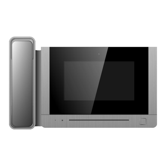
2. Guard unit Part Name Description Handset RJ11 Connector Interface for helical line Power Indicator Red led when power on Screen 7-inch digital TFT LCD Speaker Door Release Button Press button for releasing door lock RJ45 Connector Interface for RJ45 6/28 MLŞ14-67/04/21.06.2021... -
Page 7: Connection Diagram
D. CONNECTION DIAGRAM E. INSTALLATION 1. Indoor Monitor Monitor installation location • Standard monitor installation height is about 1,500mm where screen center is at eye level; • In this case, wall-hanging metal center is 1,450mm above ground level. Wiring and installation of indoor monitor •... -
Page 8: Guard Unit
2. Guard unit Wiring and installation of guard • Place the guard unit on a level desktop; • Fix the bracket on the behind of the monitor with screw; • Pull the cable out and connect the system according to 4.2 wiring diagram. F. -
Page 9: Emergancy Call
• Icon Definition No network indicator [do not disturb] mode indicator Set the monitor for leaving or presence mode (default password: 9999) Remark: • The guard unit doesn't have this two icon. • The four zones trigger type are all 24h instant, the main page icon is always leaving mode; •... -
Page 10: Icon Definition
➢ Icon Definition Capture a picture Adjust ringtone volume Mute Release the door lock Talk Terminate the talk 2. Contacts • Press the [call] icon on main screen and the screen will enter the call page: • In the call page, you can press the [Contacts] icon to review the contacts and click the contact you want to call. -
Page 11: Call Records
3. Call Records In the call page, you can press the [Records] icon to review the call records. You can also enable “Missed” by the checkbox to review missed calls. Press to review the voice message from visitor. Press to review the picture automatically captured. Press to start the call. -
Page 12: General Settings
Remark: • Long press a call records for 2s, you can delete the call record or delete all records. • Pictures and voice messages are linked to call records, support 100pcs max. 4. General settings In the call page, you can press the [Setting] icon to enter the setting page. In this page, you can •... -
Page 13: Intercom
5. Intercom In the call page, you can input the intercom address of the monitor you want to call and then press [Call] icon to start the call. When call in, it will show as below: There are several ways to input the intercom address: •... - Page 14 • You can press the [Inbox] icon to review the received message; you can also delete, forward and reply messages. • You can press the [Outbox] icon to review the messages that have been sent, you can also delete, forward and reply messages. •...
-
Page 15: Monitor Function
e. Monitor Function Press the [Monitor] icon on main screen, select the door panel or camera you want to monitor and then enter the monitoring mode (support up to 19 door panels and 32 cameras). Remark: • Indoor monitor can only show the connected block’s door panel; Guard unit can show the all- blocks’... -
Page 16: Alarm Function
f. Alarm Function 1. Indoor monitor When the alarm is triggered, the monitor will buzzer at the same time; you can enter the alarm password and press the icon to turn off the alarm (default password: 9999). Press the [Alarm] icon on main screen and enter the password (default password: 9999), the screen will be shown as follows: •... -
Page 17: Guard Unit
Set the zone name (default name: Zone1; Zone2; Zone3; Zone4); • Set the type of sensor (Gas/Smoke/Water/Magnetic/Pir/Custom Type); • Set the trigger type of the sensor (Instant/Delay/24h Instant/ByPass); • Set the alarm delay time (1~99s); • Set the alarm activation delay time (1~99s); •... -
Page 18: Lim70 Ip Interkom Alarm Connections
3. LIM70 IP Interkom Alarm Connections 18/28 MLŞ14-67/04/21.06.2021... -
Page 19: Picture Review
g. Picture Review Press the [Storage] icon on main screen, you can press the corresponding list directly to review the picture. You can also delete the picture or press icon to review the picture. Remark: • In the storage page, you can only review the manually captured pictures. •... -
Page 20: Engineering Setting
• In [Clean Mode] setting page, you can press the [start] icon to start cleaning and no buttons will be triggered during the cleaning process. • In [Reset] setting page, you can format micro-SD card and restore monitor to factory settings (including language / touch tone and general user settings will be restored to default). - Page 21 When the IP camera function is enabled, you can input the IP address, user name, password and select the stream mode: Main stream/Sub stream(the current system only support sub stream),then you can press the icon to confirm the setting. Remark: •...
-
Page 22: Elevator Function
G. ELEVATOR FUNCTION a. General You can set the monitored room number to 821~839, then press the confirm icon, this monitor will be set as elevator monitor. In case emergency, you can use the elevator monitor to call the guard or monitor. ➢... -
Page 23: Connecting The Module To The Ip Intercom Network
b. Connecting The Module To The IP Intercom Network See „Picture“ below for detailed wiring diagram. A general diagram of the connection circuits of the elevator monitor to be installed in the elevators is given below. All connectors seen in the diagram together with the elevator monitor, EoP connection device, adapter and poe switch must be obtained from the company. -
Page 24: Methods Of Callingin Emergancies From The Elevator Device
c. Methods Of Calling In Emergencies From The Elevator Device When the EMERGENCY CALL icon on the left of the elevator device screen is touched, the predefined security number on the icon is called immediately. The conversation starts when the other party answers. The maximum duration of the speech is 3 minutes. -
Page 25: Network Connection Diagram Of Elevator Intercom Device
e. Network Connection Diagram Of Elevator Intercom Device 25/28 MLŞ14-67/04/21.06.2021... -
Page 26: Introducing The Elevator To The Flat Monitor
f. Introducing The Elevator To The Flat Monitor Calling an elevator to your floor; ➢ Enter the Settings section on the home page. ➢ Activate it by pressing the icon opposite the Elevator Calling text. ➢ Enter the elevator number on your floor “1” or “2”. It could be an elevator. Enter the number on which floor the flat is on. -
Page 27: Electional Rights Of The Consumer
27/28 MLŞ14-67/04/21.06.2021... -
Page 28: Warranty Certificate
28/28 MLŞ14-67/04/21.06.2021...
Need help?
Do you have a question about the LIM 70 and is the answer not in the manual?
Questions and answers