NAD 3130 Manual
- Service manual (21 pages) ,
- Instructions for installation and operation manual (10 pages) ,
- Service manual (12 pages)
Advertisement
REAR PANEL

- AC Line Cord.
- AC Convenience Outlets.
- Speakers A.
- Speakers B.
- Phono Ground.
- Phono input.
- MM/MC Selector.
- Tuner Input.
- CD Input.
- Video Input.
- Tape Rec/Play.
- Preamp Out, Main In.
- Soft Clipping.
- Speaker impedance.
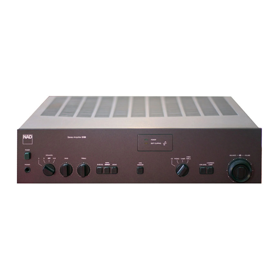
FRONT PANEL

- Power.
- Phones.
- Speaker Selector.
- Bass.
- Treble.
- Bass EQ.
- Infrasonic Filter Defeat.
- Mono.
- Tape Monitor.
- input Selector.
- Low Level.
- Loudness Compensation.
- Volume/Balance.
A NOTE ON INSTALLATION
Thic unit may be installed on any sturdy, level surface. Since its power transformer generates a magnetic hum field of moderate strength, a turntable (especially one with a moving-coil pickup cartridge) should not be located directly to the left of the amplifier nor directly above it.
The amplifier generates a modest amount of heat and thus requires some ventilation. Do not place it on a rug or other soft surface that it could sink into, obstructing the air inlets on its bottom. And be careful not to obstruct the air outlet grille on the top cover.

To prevent a fire or shock hazard, do not permit liquid or moisture to enter the amplifier. If liquid is ![]() accidentally spilled on it, immediately shut off its power and unplug its AC power cord. Allow sufficient time for complete evaporation to occur before operating the amplifier again. (If the liquid is anything but water and/or alcohol, the amplifier should be examined by a service technician before power is applied to it.)
accidentally spilled on it, immediately shut off its power and unplug its AC power cord. Allow sufficient time for complete evaporation to occur before operating the amplifier again. (If the liquid is anything but water and/or alcohol, the amplifier should be examined by a service technician before power is applied to it.)
Do not open the amplifier, or attempt to modify or repair it yourself. Refer all servicing to a qualified technician.
 The lightning flash with arrowhead, within an equilateral triangle, is intended to alert the user of the presence of uninsulated "dangerous voltage" within the product's enciosure; that may be of sufficient magnitude to constitute a risk of electric shock to persons.
 The exclamation point within an equilateral triangle is intended to alert the user of the presence of important operating and maintenance (servicing) instructions in the literature accompanying the appliance.
REAR PANEL CONNECTIONS
- AC LINE CORD
Plug the AC line cord into a "live" wall socket. - AC CONVENIENCE OUTLETS (not in U.K. model)
The AC power line cords of other stereo components may be plugged into these accessory outlets. The SWITCHED outlet is intended for all-electronic products (e.g., a tuner, equalizer, or other signal processor), and will be switched on and off by the amplifier's main POWER button. The UNSWITCHED outlet should be used to power products involving mechanical operations (e.g., a turntable or tape deck); such products should be switched on and off with their own power switches.
The UNSWITCHED outlet can also be used to power any device containing a clock timer, or a digital tuner that requires uninterrupted AC power to maintain station tuning information stored in its memory. - SPEAKERS A
![]() If the wire connecting each loudspeaker will be less than 6 meters (20 feet) long, then connections should be made using 18-gauge wire such as common lamp cord ("zip" cord), available from hardware and electrical-supply stores in either white, black, or brown insulation.
If the wire connecting each loudspeaker will be less than 6 meters (20 feet) long, then connections should be made using 18-gauge wire such as common lamp cord ("zip" cord), available from hardware and electrical-supply stores in either white, black, or brown insulation.
If the wiring to the speakers will be longer than 6 meters, heavier 16-gauge or 14-gauge wire is preferred. Heavy-duty wiring is especially desirable if you are using speakers of low impedance.
The loudspeaker terminals are heavy duty binding posts. Each binding post consists of a threaded metal shaft and a red or black screw-on bushing. Connections may be made in either of two ways.- A small hole through the threaded shaft accepts bared wires up to 16 gauge in thickness. To make connections, separate the two conductors in each speaker cable. Strip off about a half-inch (1 cm) of insulation from each, and in each conductor twist the exposed wire strands together. Unscrew the bushing a few turns to expose the hole, insert the bare speaker wire into the hole in the metal shaft, and screw the bushing down tight.
- A standard spring-type banana plug may be inserted axially into the top of each binding post. The binding posts have the %-inch (19 mm) spacing required to accept standard dual-banana plugs. Purchase dual-banana plugs and install them on your speaker cables (or purchase speaker wires with dual-banana plugs already attached), and pl ug the dual-banana connectors into the binding-post terminals.
Phasing. Stereo speakers should operate in phase with each other in order to yield a good stereo image and to reinforce rather than cancel each other's output at low frequencies. If your speakers are easily moved, their phasing can easily be checked. Make the connections to both speakers, place the speakers face-to-face only a few inches apart, play some music, and listen. Then swap the connection of the two wires at the back of ONE of the speakers, and listen again. The connection which produces the fullest, boomiest bass output is the correct one. Connect the wires securely to the speaker terminals, being careful not to leave any loose strands of wire that might touch the wrong terminal and create a partial short-circuit; then move the speakers to their intended locations.
If the speakers cannot easily be set face-to-face, then phasing must rely on the "polarity" of the connecting wires. Note that the SPEAKERS terminals on the amplifier are color •coded: in each channel the red terminal has positive " + " polarity and the black terminal is negative The terminals at the rear of the speakers are also marked for polarity, either via red and black connectors or by labels: 1, or 8 ohms for positive, O, or G for negative. As a general rule the positive (red) terminal on the amplifier is to be connected to![]() the positive terminal of the speaker, in each channel.'
the positive terminal of the speaker, in each channel.'
To facilitate this, the two conductors comprising the speaker wire in each channel are different, either in the color![]() of the wire itself (copper vs. silver) or in the presence of a small ridge or rib pattern on the insulation of one conductor. Use this pattern to establish consistent wiring to both speakers of a stereo pair. Thus if you connect the copper colored wire (or ribbed insulation) to the red amplifier terminal in the Left channel, do the same in the Right channel. At the other end of the wire, if you connect the copper colored wire (or the ribbed insulation) to the red or positive terminal on the left-channel speaker, do the same at the right channel speaker.
of the wire itself (copper vs. silver) or in the presence of a small ridge or rib pattern on the insulation of one conductor. Use this pattern to establish consistent wiring to both speakers of a stereo pair. Thus if you connect the copper colored wire (or ribbed insulation) to the red amplifier terminal in the Left channel, do the same in the Right channel. At the other end of the wire, if you connect the copper colored wire (or the ribbed insulation) to the red or positive terminal on the left-channel speaker, do the same at the right channel speaker.
- SPEAKERS B
A second pair of loudspeakers may be connected to the amplifier, using the "B" group of terminals, in the same manner as the connections made to the SPEAKERS A terminals.
If the second pair of speakers is located near the first pair and will be played simultaneously, then they must be correctly phased with respect to the first pair as well as with each other. But if the second pair of speakers is located away from the first pair (in another room, for example) or will not be played at the same time as the first pair, then their phasing need not match that of the first pair. Of course, as with any stereo speakers, the second pair still must be in phase with each other.
The SPEAKERS B terminals may also be used to connect an adapter unit for electrostatic headphones. The black terminals in each channel share a common ground.
Another useful option for the SPEAKERS B terminals is to connect a second pair of speakers wired for "ambience recovery," enhancing the apparent spaciousness of stereo recordings. Locate a pair of small loudspeakers along the side walls of the listening area, slightly behind the main listening area and as far as possible to the left and right. (Often it useful to aim such speakers upward or toward the rear, so that their sound reflects randomly off the walls before reaching you.) Connect a wire from the (L+) terminal to the positive terminal of the left-rear speaker, and a second wire from the (R+) terminal to the positive terminal of the right-rear speaker. Make no connection to the (L—) and (R—) terminals on the amplifier; instead, connect a wire from the negative terminal of the left-rear speaker to the negative terminal of the right-rear speaker. Thus wired, these rear speakers receive the left-minus-right "difference" portion of the composite stereo signal. - PHONO GROUND
If your turntable is equipped with a grounding wire (usually a green wire terminating in a U-shaped spade lug), connect it to this terminal. Turn the thumb-nut counterclockwise, place the spade lug under the nut, and tighten the thumb-nut clockwise to secure the lug. If the grounding wire has no spade lug, strip off 1 cm of insulation to expose the bare wire, twist the wire strands tightly together, insert the wire though the small hole in the shaft of the Ground terminal, and tighten the thumb-nut to fasten the wire in place,
If you encounter a persistent low-level hum or buzz in the sound, connect a wire from the Ground terminal to a true earth-ground, i.e. a copper-plated rod driven several feet into the earth. A substitute electrical ground may also prove effective: a cold water pipe, a steam radiator, or the third hole of a modern electrical wall socket. - PHONO INPUT
Plug the signal cables from your turntable into these jacks. If the cables or plugs are color-coded, refer to your turntable's instruction manual to learn which cable or plug is for the Left channel (upper jack) and which for the Right (lower jack). Be careful to insert each plug fully into the socket so that the plug's metal skirt fits tightly over the exterior of the socket. If necessary, crimp the plug's metal skirt slightly so as to obtain a tight fit with the socket.![]()
- MM/MC SELECTOR
This switch sets the input sensitivity and gain of the phono preamplifier circuit. Set it according to the output level of your phono cartridge. Set the switch at MM for cartridges of the moving magnet, induced magnet, moving flux, and![]() moving iron (variable reluctance) types, and for "high-output" moving-coil pickups, i.e., those with a rated output of 1.0.mV or greater. If your cartridge is a low-output moving-coil pickup (with a rated output of less than 1.0 mV), set the switch at MC.
moving iron (variable reluctance) types, and for "high-output" moving-coil pickups, i.e., those with a rated output of 1.0.mV or greater. If your cartridge is a low-output moving-coil pickup (with a rated output of less than 1.0 mV), set the switch at MC.
Here is another way to determine the preferred setting of the MM/MC switch. Begin by setting it to MM. After you have completed the installation and wiring of the system, play a record. With the front-panel LOW LEVEL button OUT you![]() should obtain a satisfyingly loud volume level with a VOLUME control setting between 9 0'clock and 3 0'clock. If you have to turn up the VOLUME control beyond 3 0'clock to get adequately loud sound, turn the VOLUME back down and re-set the MM/MC switch to MC.
should obtain a satisfyingly loud volume level with a VOLUME control setting between 9 0'clock and 3 0'clock. If you have to turn up the VOLUME control beyond 3 0'clock to get adequately loud sound, turn the VOLUME back down and re-set the MM/MC switch to MC. - TUNER INPUT
Connect the audio signal cable from an AM/FM (or video) tuner to this pair of jacks. - CD INPUT
Connect the audio signal cables from a digital Compact
Disc player to these jacks. The input signal will be fed to the Volume control before reaching any active circuitry so the amplifier's circuits cannot be overloaded by high-level signals from the digital player.
If you don't have a CD player, any other line-level signal source (such as a spare tape deck) may be connected to the CD input. - VIDEO INPUT
These auxiliary jacks are for any "line level" signal![]() source, such as a spare tape deck, the audio line output from a videocassette or video disc player, or a television sound tuner.
source, such as a spare tape deck, the audio line output from a videocassette or video disc player, or a television sound tuner. - TAPE REC/PLAY
The tape connections may be used with recorders of all types: cassette, micro-cassette, open-reel, digital, etc.![]() To make recordings, connect a stereo patch cord from the amplifier's TAPE OUT (REC) jacks to the recorders Ll NE IN jacks (not to its microphone inputs). To play back tapes, connect a stereo patch cord from the recorder's LINE OUT jacks to the amplifier's TAPE IN (PLAY) jacks.
To make recordings, connect a stereo patch cord from the amplifier's TAPE OUT (REC) jacks to the recorders Ll NE IN jacks (not to its microphone inputs). To play back tapes, connect a stereo patch cord from the recorder's LINE OUT jacks to the amplifier's TAPE IN (PLAY) jacks.
The TAPE REC/PLAY jacks may be used for connecting a signal processing accessory instead of a tape recorder![]() Examples of such accessories include a dynamic cange processor, a dynamic noise filter, a DBX disc decoder, or any other device whose operation depends on the setting of a signal threshold. Connect a patch cord from the TAPE OUT (REC) jacks to the processor's inputs, and another
Examples of such accessories include a dynamic cange processor, a dynamic noise filter, a DBX disc decoder, or any other device whose operation depends on the setting of a signal threshold. Connect a patch cord from the TAPE OUT (REC) jacks to the processor's inputs, and another ![]() patch cord from the processor's outputs to the TAPE IN (PLAY) jacks.
patch cord from the processor's outputs to the TAPE IN (PLAY) jacks.
Other signal processing accessories, such as a graphic equalizer or the special equalizer supplied with![]() some loudspeakers, may be connected either to the TAPE jacks or at the Preamp Out jacks. The choice is a matter of convenience.
some loudspeakers, may be connected either to the TAPE jacks or at the Preamp Out jacks. The choice is a matter of convenience. - PREAMP OUT, MAIN IN
Each channel of the amplifier includes two independent sections or stages: the control preamplifier (including the phono preamp and most front-panel controls), and the power amplifier (which provides the power to drive loudspeakers). In normal operation the preamp and power amp are connected together via factory-installed U-shaped metal jumpers that bridge the PRE-OUT and MAIN-IN jacks. Check to be sure that they are fully inserted into the jacks and that nothing is touching them.
By removing the metal jumpers (after first switching OFF the POWER), you can connect various signal-processing accessories in the path between preamp and power amp: an equalizer, a time-delay ambience reproducer, a stereo image enhancer, an electronic crossover, etc. To use a signal processor, connect a stereo patch cord from the PRE-OUT jacks to the processor's line-level input jacks, and a second patch cord from the processor's output jacks to the amplifier's MAIN-IN jacks.
NOTE: Any signal processor whose operation depends on the setting of a threshold, such as a dynamic noise filter, should be connected to TAPE REC/PLAY jacks—where the signals are unaffected by the amplifier's volume and tone controls—rather than to the PRE-OUT jacks.![]()
If you remove the metal jumpers, save them in case you may want to disconnect the signal processor and return to normal operation at a Eater time. If the jumpers should be lost, a conventional stereo patch cord can be used to connect PRE-OUT to MAIN-IN in each channel.
This unit can be used as the heart of an elaborate audiophile sound system. The preamp output is capable of driving several power amplifiers simultaneously, or of driving the long signal cables required to connect to power amps which are located near the speakers (or to "powered" active loudspeakers with built-in power amplifiers). - SOFT CLIPPING
When an amplifier is overdriven beyond its specified power output it normally produces "hard clipping" of the signal with harsh distortion and power-supply buzz as the output transistors saturate. The NAD Soft Clipping circuit gently limits the output waveform and minimizes audible distortion when the amplifier is overdriven. If your listening involves moderate peak power levels, the Soft Clipping may be left OFF. But we recommend that it be switched ON when playing music at very high levels that might exceed the amplifier's power capacity. - SPEAKER IMPEDANCE
![]()
The impedance of a loudspeaker varies with frequency, and in many loudspeakers the impedance is lowest at the frequencies where the highest power demands occur in music. In many "8Q" loudspeakers this minimum impedance is from 4 to 6 ohms, and in "40" speakers the minimum is typically 3 ohms. If you connect two sets of speakers to the amplifier, their combined impedance is approximately half the impedance of either.
For these reasons, all NAD amplifiers and receivers are designed to produce maximum power output into impedances of 2 to 6 ohms at the 4Q (NORMAL) setting of the Impedance selector. If you are not sure of the true impedance of your speakers, or if you are connecting two pairs of speakers, leave the Impedance switch at 4Q (NORMAL).
![]() If you are using a single pair of loudspeakers whose true impedance is above 6 ohms at all frequencies, you can optimize the amplifier for maximum power delivery at this higher impedance by re-setting the switch to 8Q (HGH).
If you are using a single pair of loudspeakers whose true impedance is above 6 ohms at all frequencies, you can optimize the amplifier for maximum power delivery at this higher impedance by re-setting the switch to 8Q (HGH).
To prevent accidental re-setting, the Impedance switch is held by a slotted bracket which is fastened by a screw next to the switch. Use a small screwdriver to loosen the bracket screw, turning it about a half-turn counter-clockwise, and then slide the switch to the new position. The bracket will move with the switch. Tighten the screw to secure the switch in its new position.
![]()
If the impedance switch is set to 8Q (HIGH) with loudspeakers whose true impedance is lower than 6 ohms, or with two pairs of speakers connected in parallel, the amplifier will tend to overheat and shut down when![]() operated at high output levels. The amplifier will resume normal operation after it cools; but such abuse could also cause internal fuses to blow in order to protect the amplifier. If this occurs, return the amplifier to your dealer for service.
operated at high output levels. The amplifier will resume normal operation after it cools; but such abuse could also cause internal fuses to blow in order to protect the amplifier. If this occurs, return the amplifier to your dealer for service.

NOTE: Some NAD components are equipped with dual or multi-voltage transformers (which is indicated on the back panel). if you wish to change the voltage, please bring your unit to an authorized NAD service technician for internal conversion.
FRONT PANEL CONTROLS
- POWER
Depress this button to switch on the amplifier and any other equipment plugged into the SWITCHED convenience outlet on the rear panel. To switch the power off, depress the button again and release it.
If you prefer, you may leave the POWER switch permanently engaged and use an external switch (such as a clock timer) to turn the power on and off. - PHONES
Plug stereo headphones in here. The circuit will provide proper drive signals for all conventional stereo headphones regardless of their impedance, with just one exception: electrostatic headphones usually are supplied With an adapter unit which must be connected directly to the speaker terminals on the rear panel.
Before plugging any headphones in, turn down the VOLUME control for safety. And when you are not listening to the headphones it is wise to unplug them from the PHONES jack. Otherwise, when not wearing the phones you might inadvertently turn up the volume to a high level and feed dangerously strong signals to the headphones.
You may freely use headphone extension cables. If you want to use a headphone Y-connector to drive two headsets simultaneously, they should be identical models. Connecting together two headphones that differ widely in impedance usually will produce a substantial loss of volume in the headset having the higher impedance (or in both). - SPEAKER SELECTOR
When this switch is set to "A", sound is heard only from the loudspeakers connected to the SPEAKERS A terminals on the rear panel. When the switch is set to "B," the SPEAKERS A terminals are shut off and sound is heard only from the loudspeakers connected to the SPEAKERS B terminals. At the 'A+B" setting the amplifier's output power is fed to both sets of speakers in parallel. At the "OFF" setting both sets of speakers are silenced.
Thus if you have your main stereo speakers wired to the "A" terminals and a set of extension speakers Wired to the "B" terminals, you can choose to hear only the main speakers (A), only the extension speakers (B), or both (A + B).
The amplifier's output signal is present at the PHONES jack at all settings of the SPEAKERS selector o vitch. When using headphones it normally is advisable to switch OFF the loudspeakers. Then the VOLUME control may freely be used to adjust the loudness level in the headphones with no fear of overdriving the speakers or disturbing neighbors.
If you have connected an adapter unit for electrostatic headphones to the SPEAKERS B terminals, you can use the SPEAKERS selector to switch between your main stereo speakers (A) and the headphones (B).
If you have connected speakers wired for "ambience recovery" to the SPEAKERS B terminals, you can use the SPEAKERS selector to listen to conventional stereo (A), to switch off the main speakers and listen only to the stereo L-minus-R "difference" signal in the rear speakers (B), or to listen to spatially enhanced stereo (A+ B). You will find that the stereo difference signal is usually lacking in bass. If the difference signal is very weak, the recording lacks![]() stereo separation.
stereo separation. - BASS
The Bass control adjusts the relative level of the low frequencies in the sound. The response of the amplifier is flattest when the control is set in the detent at the 12 0'clock position, Rotation of the knob to the right (clockwise) increases the level of low-frequency sounds, and rotation counter-clockwise decreases their level. Adjust the Bass control to achieve the tonal balance that sounds most natural to you.
At moderate rotations away from center the effect of the Bass control is subtle, because its action is confined to the lowest audible frequencies where significant energy is seldom found in recordings. Only at large rotations away from center is there a substantial boost or cut at the mid-bass frequencies that are common in music. - TREBLE
The Treble control adjusts the relative level of the high frequencies in the sound, The response of the amplifier is flattest when the control is set in the detent at the 12 0'clock position. Rotation of the Treble control to the right (clockwise) increases the level of high-frequency sounds, and rotation counter-clockwise decreases their level. Adjust the Treble control to achieve the tonal balance that sounds most natural to you.
Boosting the Treble increases the brilliance and clarity of details in the sound, but also makes any noise more prominent. Turning down the Treble makes the sound mellower while suppressing hiss and record surface noise; but too much Treble roll-off will make the sound dull. - BASS EQ.
This circuit boosts the lowest bass frequencies, those below 60 Hz. In virtually all loudspeakers the useful output rolls off at frequencies below the woofer/cabinet resonance (which typically occurs between 40 and 70 Hz). The BASS EQ circuit compensates for this roll off, extending the useful response of the speakers significantly lower in frequency.
If your loudspeakers already have extended and powerful deep-bass response, the BASS EQ provides other benefits:
- It helps to correct the rolled-off bass in some recordings.
- It provides effective "loudness compensation" to restore subjectively correct tonal balance at low volume levels.
- It helps to compensate for listening-room acoustics.
("Standing waves" in the room tend to weaken the low bass and reinforce the mid-bass at typical listening positions.)
Oi course very low frequencies are not found in all music, nor in all recordings, so the effect of the BASS EQ often won't be obvious. Sometimes you may find that switching it in and out does not produce any apparent change in the sound, simply because the recording contains no energy at very low frequencies. But usually the BASS EQ will provide an audible (and occasionally a dramatic) strengthening oi the deepest bass.
The BASS EQ circuit also includes an infrasonic filter that rolls off the response below 25 Hz to prevent inappropriate amplification of non-musical signals below the![]() audio range.
audio range.
![]()
Be prepared to switch off the equalization when playing recordings (especially digitally mastered discs) that contain unusually powerful recorded bass. The combination of a high playback volume level, the BASS EO, and a bass-heavy input signal could overdrive the amplifier into clipping and—more important—overdrive your woofers beyond their safe excursion limits, causing the voice-coils to clatter against the magnet back-plates, (This risk is particularly serious with small woofers, those smaller than six inches in diameter, which usually are not designed to accept high power levels at the lowest frequencies.) As long as a speaker sounds good it probably is OK; but distorted or unmusical sounds, such as clattering or buzzing, signal distress in a woofer.
Be alert, also, for signs of acoustic feedback (in which the low-frequency vibrations from the speakers are picked up by the record-playing stylus and are re-amplified). If you encounter a sustained low-frequency roar, or frequent groove-jumping, immediately turn down the Volume and switch off the BASS EQ until a more nearly vibration-free mounting for the turntable is found.
- INFRASONIC FILTER DEFEAT
The output from a record player usually contains strong but inaudible impulses at infrasonic frequencies (below 20 Hz) due to disc warps, stylus/tonearm resonance, and vibrations reaching the turntable. If these are amplified at full strength, they may waste amplifier power and produce excessive woofer cone excursions, muddying the sound.
The infrasonic filter attenuates these unwanted signals. The filter is normally in-circuit (with the button OUT), and it is especially desirable to have it in-circuit when a large low frequency boost is being applied via the BASS control.
If you want to bypass the infrasonic filter, depress the INFRA DEFEAT button. As long as the button is OUT, the filter is active.
![]() A second infrasonic filter is included in the BASS EQ circuit and is automatically engaged when the bass equalization is used. It is not affected by the INFRA DEFEAT button.
A second infrasonic filter is included in the BASS EQ circuit and is automatically engaged when the bass equalization is used. It is not affected by the INFRA DEFEAT button. - MONO
This button blends the two stereo channels together to produce monophonic sound. This blend minimizes rumble and surface noise in old monophonic records. The button must be OUT for normal stereo listening. - TAPE MONITOR
When this button is pressed it lets you hear the playback signal from your tape recorder (or any other device connected to the TAPE IN (PLAY) jacks on the rear panel). If you have a signal-processing accessory (such as a graphic equalizer or dynamic expander) connected to the TAPE jacks, pressing TAPE MONITOR allows you to hear the processed signal.
The TAPE MONITOR button affects only that you hear, not what is being recorded. The program source chosen by the INPUT SELECTOR is always fed to the REC jacks for recording or processing, regardless of any other controls.
![]()
If you have nothing connected to the TAPE REC/PLAY jacks, or have a tape deck connected but a ot running, then when you press TAPE MONITOR you will hear nothing but silence—regardless of what other button; you may press! To disengage the TAPE MONITOR circul and restore the normal signal path, press the TAPE MONITOR button again and release it.![]()
The standard purpose of the TAPE MONITOR is to allow you to listen to recorded tapes, and also to check on tape recordings as they are being made. If you have a three-head tape deck that allows off-the-tape monitoring during recording, engaging the TAPE MONITOR switches on both the amplifier and the tape deck will let you hear the playback signal from the tape immediately after it is recorded, so that you can check on its quality.
To make tape recordings on a recorder attached to the TAPE REC/PLAY jacks, simply use the INPUT SELECTOR switch to select the program source that you want to record from (CD, PHONO, TUNER, etc.). The recording will not be affected by any control but the INPUT SELECTOR; thus you may vary the volume and tone controls, the TAPE MONITOR switch, etc., without altering the recording that is being made.
COPYING TAPES: If you want to copy a recording from one tape deck to another, connect the "copying" or "dubbing" recorder (with a blank tape) to the TAPE REC/PLAY jacks. Connect the playback cable from the "source" deck (the machine containing the tape to be copied) to the Video input jacks. Select Video on the INPUT SELECTOR switch in order to hear the source tape and feed its signal to the copying recorder. If you then press the TAPE MONITOR button, you will hear the signal after it has passed through the copying recorder's electronics.
If you need greater flexibility in connecting and copying among multiple tape decks, purchase an inexpensive switch-box, connect it to the TAPE REC/PLAY jacks, and connect the tape decks to the switch-box. (Example: the Radio Shack #42-2105 switch-box contains switches for monitoring and copying among three tape decks.)
- INPUT SELECTOR
This switch selects the input signal for the amplifier. The selected input signal will be heard through the loudspeakers or headphones as long as the TAPE MONITOR button is disengaged. The selected input signal will also be fed out through the TAPE OUT (REC) jacks for tape recording or signal processing. - LOW LEVEL
This button reduces the volume of the amplified sound by approximately 20 decibels. It has no effect on the signal fed to the TAPE OUT (REC) jacks for taping or processing. The LOW LEVEL switch has several practical uses:
- It extends the useful range of the Volume control. With high-output signal sources, with efficient loudspeakers, or with sensitive headphones, you may find that the sound is too loud over most of the range of the Volume control, so that you are restricted to using only settings near the lower end of the control range. In this case, engaging the Low Level switch to reduce the output level will allow you to use the full range of the Volume control for normal listening.
- It provides optimum signal-to-noise ratio for low-level listening in quiet environments. For example, if you are listening to soft music late at night when the surroundings are quiet, the Low Level switch minimizes the already-low residual noise of the preamplifier and tone-control circuits, ensuring noise-free listening.
![]()
- It provides a convenient temporary cut in volume, to be used while answering the telephone for instance. When the button is pressed again and released, it restores the volume precisely to the pre-set level.
- LOUDNESS COMPENSATION
This button engages a "loudness compensation" circuit which, at low-to-medium settings of the Volume control, boosts the bass response of the amplifier in order to compensate for the human ear's diminished sensitivity to low frequency sounds at low loudness levels. The circuit also Provides a slight treble boost to overcome the "masking" of subtle high-frequency details by background noise.
![]() Instead of using this button, you may prefer to use the tone controls and BASS EQ to obtain the tonal balance +hat sounds most natural to you, at any volume level.
Instead of using this button, you may prefer to use the tone controls and BASS EQ to obtain the tonal balance +hat sounds most natural to you, at any volume level. - VOLUME/BALANCE
The knurled outer ring of this two-section knob ic the Volume control, which adjusts the overall loudness of the sound. The control is designed for accurate tracking of the two channels, so that the stereo balance will not shift noticeably as the Volume control setting is varied.
The center section of the dual knob is the Balance control, which adjusts the relative levels of the left and right channels. A detent at the 12 0'clock position marks the point of equal balance. Rotation of the knob to the right (clockwise) decreases the level of the left channel so that only the right channel is heard, thus shifting the sonic image to the right. Rotation of the knob to the left shifts the sonic image toward the left speaker.
Adjust the Balance control to produce a natural spread of sound across the space between the speakers, with any monophonic sound (such as a radio announcer's voice)![]() appearing as a phantom image centered midway between the speakers.
appearing as a phantom image centered midway between the speakers.
Ideally the detented center position of the Balance control would be its normal setting. But several common circumstances may cause an unequal balance between the channels, requiring a compensatory off-center setting of the Balance control to restore the most uniform spread of stereo sound between the speakers. Examples include unequal output from the two channels of the phono cartridge, different acoustical environments around the two loudspeakers, or simply a listening position that is closer to one speaker than to the other.
These controls do not affect the signals fed to the TAPE RE Cording jacks.
A NOTE ON OVERLOAD PROTECTION
Because NAD amplifiers sound so clean and musical when driven beyond their nominal power ratings and when used to drive low-impedance loudspeakers, you may be tempted to stress this amplifier beyond its design capacity. It can safely and cleanly drive impedances as low as 2 ohms with wide-range musical signals whose peak level is twice the rated power or more, but it may overheat if called upon to deliver high power continuously into a low impedance.
Thus you may play music at volume levels which cause the brief transient peaks and climaxes in music to exceed the amplifier's rated power by a considerable margin (and with Soft Clipping the music will continue to sound good at those high peak levels). But if you overdrive the amplifier continuously, rather than only on brief musical peaks, the output transistors may overheat.
This is particularly likely if you set the SPEAKER IMPEDANCE switch to 8 OHMS and then try to drive ve ry low impedances at high volume levels. Severe abuse of this type could cause internal fuses to blow in order to protect the amplifier. These fuses are not intended to be replaced by the user; if the amplifier shuts down you should return it for service.
If this occurs, you should examine whether a pattern of unintended abuse may have contributed to the failure ![]() For example you may have a loose strand of speaker wi re causing a partial short-circuit either at the speakers or at the amplifier's speaker terminals. The impedance of your weak ers may be lower than you think; if you are not sure, set the SPEAKER IMPEDANCE switch to 4 OHMS. You may combining maximum bass boost with high volume settings. Or you may simply be playing the music at continuously hi*h power levels that demand a larger amplifier with high-»wer transistors and bigger heat-sinks.
For example you may have a loose strand of speaker wi re causing a partial short-circuit either at the speakers or at the amplifier's speaker terminals. The impedance of your weak ers may be lower than you think; if you are not sure, set the SPEAKER IMPEDANCE switch to 4 OHMS. You may combining maximum bass boost with high volume settings. Or you may simply be playing the music at continuously hi*h power levels that demand a larger amplifier with high-»wer transistors and bigger heat-sinks.
TROUBLE-SHOOTING GUIDE
| SYMPTOM | POSSIBLE CAUSE |
No sound | Power not on. Line cord unplugged. Tuner selected but tuned to a blank frequency between stations. VIDEO input selected with no video (or other auxiliary source) playing. Tape Monitor engaged with no tape playing. Speaker switch set to OFF, or to B when speakers are connected only to the "A' terminals. Internal fuses blown to protect the amplifier from short-circuited speaker wires or from overheating caused by overdriving the amplifier into a low impedance with the Impedance selector at 8 ohms. |
No sound in one channel | Balance control turned full-left or full-right. Loudspeaker connecting wire pulled loose (check all connections, both at speakers and at the amplifier). Pre-Out/Main-In jumper pulled out, missing, or making contact with any metal object. Connecting cable pulled loose or making poor contact in socket. Rotate plugs in sockets to restore contact Broken wire in a connecting cable. Wiggle all cables, especially where they enter plugs. Dirty contact in a switch. Exercise all front-panel switches to restore clean wiping contact. |
Low-frequency hum in phono | Turntable grounding wire not connected. Ground-loop hum. Install polarized AC plugs properly in polarized wall sockets (in which one slot is longer than the other). Try reversing any nonpolarized plugs in their sockets, to find the orientation that yields the least hum. Turntable located too close to the amplifier (especially to its left). Locate the turntable to the right of the amplifier. Phono cables routed too close to the amplifier's power transformer (at left-rear). Phono plugs making poor contact in socket. (Also check any phono plugs in the turntable base.) |
Hum in tape playback | Tape deck located too close to amplifier (directly above or below). Tape deck located too close to television set. Plugs making poor contact in sockets. |
Weak bass; diffuse stereo imaging | Speakers wired out of phase. Swap connections at the back of ONE speaker. Very weak or no bass may be caused by a defective (burnt-out or blown) woofer. |
Documents / ResourcesDownload manual
Here you can download full pdf version of manual, it may contain additional safety instructions, warranty information, FCC rules, etc.
Advertisement


Need help?
Do you have a question about the 3130 and is the answer not in the manual?
Questions and answers