Table of Contents
Advertisement
Quick Links
Advertisement
Table of Contents

Summary of Contents for MACHINE SOLUTIONS BEAHM DESIGNS 320-B
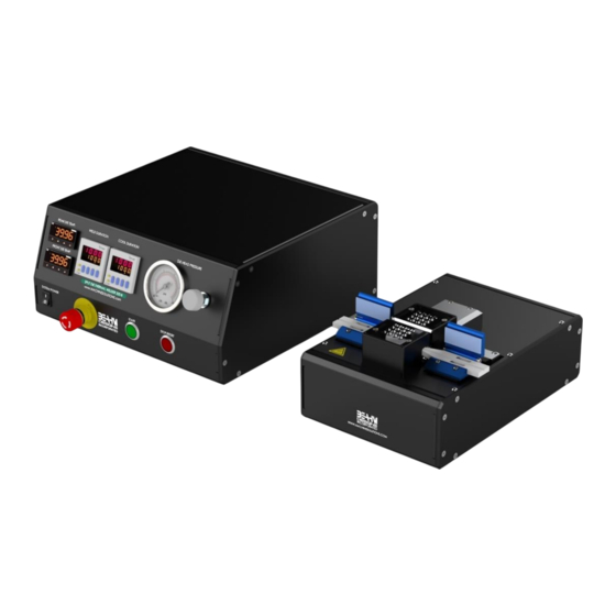
- Page 1 BEAHM DESIGNS SPLIT DIE THERMAL BONDER MODEL 320-B...
- Page 2 The Machine Solutions Inc. products shown and described in this catalog may be covered by one or more of the following US Patents: #6,629,350, #6,968,607, #6,925,847, #6,988,881, #6,931,899 and #7,069,794. Other US and International Patents Pending. Machine Solutions, MSI, and 320B are trademarks or service marks of Machine Solutions Inc.
-
Page 3: Table Of Contents
Diagnostics And Troubleshooting ....................16 Specifications ..........................17 Facility Requirements ....................... 17 Critical Parts ........................... 18 Customer Support And Satisfaction ....................19 Warranty And Limitations ......................20 Appendix A ............................ 22 © Copyright. Machine Solutions Inc. All Rights Reserved PM-60060 Rev. F... -
Page 4: List Of Figures
Table 1. Control and Display Functions (Front Panel)................... 8 Table 2. Control and Display Functions (Back Panel) ..................9 Table 3. Diagnostics and Troubleshooting ....................16 Table 4. System Specifications ........................17 Table 5. Critical Spare Parts ..........................18 PM-60060 Rev. F © Copyright. Machine Solutions Inc. All Rights Reserved... -
Page 5: Welcome
Equipment User Manual ELCOME Machine Solutions, Inc. (MSI) would like to take this opportunity to thank you for purchasing your new 320-B Split Die Thermal Bonder machine. At MSI, we are dedicated to bringing innovative process development solutions to both medical device and nonmedical organizations. -
Page 6: User Alerts
Connect the electrical and pneumatic umbilicals to the die base unit. Connect the power cord to the main unit. Connect the air supply to the system and then to a clean, dry, and filtered compressed air source. PM-60060 Rev. F © Copyright. Machine Solutions Inc. All Rights Reserved... -
Page 7: Set Up And Configuration
More important than the guide design and dimensions is alignment with the die heads. Refer to the maintenance section for the alignment procedure. Figure 1. Grip/Positioning nests © Copyright. Machine Solutions Inc. All Rights Reserved PM-60060 Rev. F... -
Page 8: System Controls And Features
Toggles system power and air on and off E-Stop Interrupts all system power and air Start switch Initiates process sequence 10 Stop/Reset switch Interrupts the process sequence and resets the system timer PM-60060 Rev. F © Copyright. Machine Solutions Inc. All Rights Reserved... -
Page 9: Figure 3. 320-B Split Die Thermal Bonder Back Panel
3 Industrial System Air Connection Controls system air supply 4 Foot Switch Allows connection to foot pedal 5 Power Entry Module Connects to power cord 6 Cooling Air Regulator Controls flow of cooling air © Copyright. Machine Solutions Inc. All Rights Reserved PM-60060 Rev. F... -
Page 10: Parameter Settings
Depress the STOP/RESET switch to reset the timer to the new value. Adjusting Die Pressure • Rotate the regulator knob clockwise or counterclockwise until the pressure gauge displays the desired value. PM-60060 Rev. F © Copyright. Machine Solutions Inc. All Rights Reserved... -
Page 11: Omega Platinum Temperature Controller
Level 1 = INIt, PRoG, and oPER Navigate to oPER (Operating Mode). Select oPER. Navigate to RUN. Select the RUN. Displays the current temperature. © Copyright. Machine Solutions Inc. All Rights Reserved PM-60060 Rev. F... -
Page 12: Resetting The Temperature Controller
Equipment User Manual Resetting the Temperature Controller Refer to Appendix A on page 22 for resetting the temperature controller and all temperature control settings. PM-60060 Rev. F © Copyright. Machine Solutions Inc. All Rights Reserved... -
Page 13: Run Process
2. Lower the guide covers onto the product. 3. Depress the start button or foot switch to initiate the process sequence. 4. Upon completion of the cooling cycle, lift the guide covers and remove the assembly. © Copyright. Machine Solutions Inc. All Rights Reserved PM-60060 Rev. F... -
Page 14: Maintenance
Manually close the die heads and ensure that they are aligned left-to-right and, while holding the heads together, tighten the base fasteners. Fully insert each thermocouple into each die head and lightly tighten each set screw. Re-install each upper heat shield. PM-60060 Rev. F © Copyright. Machine Solutions Inc. All Rights Reserved... -
Page 15: Exchanging Vee Guides
8. Close the guide covers. 9. Manually open and close the die heads and verify alignment. 10. Re-adjust each axis as required to obtain optimum alignment. © Copyright. Machine Solutions Inc. All Rights Reserved PM-60060 Rev. F... -
Page 16: Diagnostics And Troubleshooting
• Temperature controller • Replace temperature .Err code in display • Software failure controller • IEC power cord not fully • Verify installation System will not power on connected PM-60060 Rev. F © Copyright. Machine Solutions Inc. All Rights Reserved... -
Page 17: Specifications
+/- 0.03% F.S. Air Flow 0-60 psi Facility Requirements • Voltage: 120-240 VAC, 50/60 Hz • Wattage: 10 amps (500 watts) • Compressed Air: 100-125 psi, clean dry compressed air © Copyright. Machine Solutions Inc. All Rights Reserved PM-60060 Rev. F... -
Page 18: Critical Parts
Thermocouple 3054593-101 Blank Die Heads (0.5”) (Pair) 1348043-001 Air Pressure Gauge 1161899-001 Temperature Controller 1143311-001 Solid State Relay 1143287-001 Relay, 24 VDC 1343250-001 Valve, 2 Way 1330445-003 Valve, 5-2 PM-60060 Rev. F © Copyright. Machine Solutions Inc. All Rights Reserved... -
Page 19: Customer Support And Satisfaction
UPPORT ATISFACTION Machine Solutions Inc. is proud of the advanced engineering and quality construction of each piece of equipment that we build. It is our goal to provide equipment that exceeds the expectations of the customer. By implementing the highest standards and applying our experience to provide a quality product, we maintain an ongoing, positive working relationship with all our customers. -
Page 20: Warranty And Limitations
IMITATIONS General Warranty Machine Solutions Inc. (MSI) warrants its products to be free from defects in material and workmanship in normal everyday use and service for a period of one year from the date of shipment from the factory in Flagstaff, Arizona. MSIs obligation under this warranty shall be limited to the repairing or replacing of the product or parts thereof which upon MSIs inspection reveals them to be defective. - Page 21 By accepting and using the equipment, you agree to defend and indemnify Machine Solutions, Inc., its officers, directors, employees, and agents, from and against any claims of infringement as a result of your use of the equipment.
-
Page 22: Temperature Controller Layout And Description Of Button Actions
• Mitigate user errors. • User accountability. For additional information, please contact service@machinesolutions.com Temperature Controller Layout and Description of Button Actions Figure A-1. Controller Layout Figure A-2. Description of Button Actions PM-60060 Rev. F © Copyright. Machine Solutions Inc. All Rights Reserved... -
Page 23: Auto Tune Temperature Controller(S)
Auto Tune Temperature Controller(s) Please note, the Omega temperature controllers have been auto tuned and are set for optimal performance. Contact Machine Solutions for further diagnostics and instructions. The Autotune function will select the tuning algorithm depending on the stability of current process and the error difference between current process and the Control Setpoint (SP1). - Page 24 Level 1 = INIt, PRoG, and oPER Navigate to PRoG (Programming Mode). Select PRoG. Navigate to Pld. Select Pld. Navigate to A.to. Select A.to Set to 5.00 minutes or above PM-60060 Rev. F © Copyright. Machine Solutions Inc. All Rights Reserved...
- Page 25 5. (PRoG> Pld > GAIN > _d_ > 23.87) Level Level Level Level Level Level Level Notes GAIN 23.87 Manual Derivative Factor setting Navigate to _d_ Select _d_ Enter 23.87 © Copyright. Machine Solutions Inc. All Rights Reserved PM-60060 Rev. F...
- Page 26 Enable fuzzy logic adaptive tuning Navigate back to level 3 by pushing the button. Navigate to tUNE Select tUNE Select StRt Auto Tune starts and displays DONE when completed PM-60060 Rev. F © Copyright. Machine Solutions Inc. All Rights Reserved...
-
Page 27: Changing Temperature Units On The Temperature Controller
Navigate to °F Select °F Select up button to go back to level 1 Navigate to oPER Select oPER “RUN” will be displayed. Back to temperature readout and normal operating status. © Copyright. Machine Solutions Inc. All Rights Reserved PM-60060 Rev. F... -
Page 28: Resetting The Temperature Controller(S) Back To Factory Defaults
Navigate to INIt (Initialization Mode). Select INIt. Navigate to F.dFt Select F.dFt Navigate to ok? Select ok? The controller will now be reset. Next, enter the following MSI settings in red. PM-60060 Rev. F © Copyright. Machine Solutions Inc. All Rights Reserved... -
Page 29: Resetting The Temperature Controller(S) Back To Msi Settings
Navigate to INIt (Initialization Mode). Select INIt. Navigate to RdG (Reading Formats). Select RdG. Navigate to dEC.P (Decimal-point Format). Select dEC.P. Navigate to FFF.F (One decimal place). Select FFF.F. © Copyright. Machine Solutions Inc. All Rights Reserved PM-60060 Rev. F... - Page 30 Navigate to INIt (Initialization Mode). Select INIt. Navigate to RdG (Reading Formats). Select RdG. Navigate to the FLtR (Filter parameter). Select FLtR. Navigate to 8 (0.4 s). Select 8. PM-60060 Rev. F © Copyright. Machine Solutions Inc. All Rights Reserved...
- Page 31 Navigate to INIt (Initialization Mode). Select INIt. Navigate to RdG (Reading Formats). Select RdG. Navigate to bRGt (Brightness parameter). Select bRGt. Navigate to HIGH (High display brightness). Select HIGH. © Copyright. Machine Solutions Inc. All Rights Reserved PM-60060 Rev. F...
- Page 32 Navigate to RSM. Note: RSM – Program runs automatically at startup if not previously in fault state. Select RSM. 8. Configure the USB port CoMM Configure the USB port PM-60060 Rev. F © Copyright. Machine Solutions Inc. All Rights Reserved...
- Page 33 Either or both Alarm configurations can be assigned to multiple outputs. The ALM.1 and ALM.2 configuration menus have all the same settings and function in the same manner. Select ALM.1. © Copyright. Machine Solutions Inc. All Rights Reserved PM-60060 Rev. F...
- Page 34 Note: After selecting HI.Lo setting, tyPE parameter should be showing in window. Navigate to A.CLR (Alarm Color parameter). Select A.CLR. Navigate to REd (Alarm conditions are displayed in red). Select the REd. PM-60060 Rev. F © Copyright. Machine Solutions Inc. All Rights Reserved...
- Page 35 Ramp/Soak event output; the output can also be turned off. Select ModE. Navigate to ALM.1. Note: ALM.1 – Set the output to be an Alarm using the ALM.1 configuration Select ALM.1. © Copyright. Machine Solutions Inc. All Rights Reserved PM-60060 Rev. F...
- Page 36 Note: ModE – Allows the output to be set up as a control, Alarm, retransmission, or Ramp/Soak event output; the output can also be turned off. Select ModE. Navigate to oFF. Note: oFF – Turn off the output channel Select oFF. PM-60060 Rev. F © Copyright. Machine Solutions Inc. All Rights Reserved...
- Page 37 Note: ModE – Allows the output to be set up as a control, Alarm, retransmission, or Ramp/Soak event output; the output can also be turned off. Select ModE. Navigate to Pld. Note: Pld - Set the output to Proportional-Integral-Derivative (PID) Control Mode. Select Pld. © Copyright. Machine Solutions Inc. All Rights Reserved PM-60060 Rev. F...
- Page 38 Note: RVRS – Off when Process Value is > Setpoint, and on when Process Value is < Setpoint (e.g., heating); deadband is applied below Setpoint (factory default) Select RVRS. A full description of features can be found here: https://assets.omega.com/manuals/M5451.pdf. PM-60060 Rev. F © Copyright. Machine Solutions Inc. All Rights Reserved...
-
Page 39: Die Head Sizing
6. Machine the die heads to width based on value in Step 2. 7. Bore hole through heads .003” less than the diameter value in Step 4. 8. For Balloon Shield bore size, add .005” to the product OD (without sleeve). © Copyright. Machine Solutions Inc. All Rights Reserved PM-60060 Rev. F... - Page 40 Equipment User Manual Figure B-1. Die Head Sizing PM-60060 Rev. F © Copyright. Machine Solutions Inc. All Rights Reserved...
Need help?
Do you have a question about the BEAHM DESIGNS 320-B and is the answer not in the manual?
Questions and answers