
Subscribe to Our Youtube Channel
Related Manuals for Franklin Electric INCON 1250B

Summary of Contents for Franklin Electric INCON 1250B
- Page 1 GRID SOLUTIONS INCON® PROGRAMMABLE POSITION MONITOR I N S T A L L A N D P R O G R A M M I N G G U I D E 000-1077 r11 MODEL NUMBER 1250B...
- Page 2 Copyright © 2024 Franklin Electric Co., Inc., Madison, WI 53718. All world rights reserved. No part of this publication may be stored in a retrieval system, transmitted, or reproduced in any way, including, but not limited to, photocopy, photograph, magnetic, or other record, without the prior written permission of Franklin Electric.
-
Page 3: Table Of Contents
Contents 1 Introduction ........................1 1.1 Documentation ......................1 1.1.1 Symbol Legend ....................1 2 Safety/Security ........................2 2.1 General Safety Information..................2 2.2 Documentation Availability ..................2 2.3 Hazard Assessment ....................2 2.4 Required Personal Protective Equipment (PPEs) ............3 2.5 Cyber Security ......................3 3 Pre-Installation Overview ....................4 3.1 Upon Receipt of Item(s) .....................4 3.2 Technical Overview ....................4 3.2.1 Specifications ....................5... - Page 4 5.3.4.1 Mode 1 – Linear Scaled Mode ............19 5.3.4.2 Mode 2 – Non-Linear Scaled Mode ..........20 5.3.4.3 Modes 16 & 17 – Base 1 Uni-Polar Segmented ......21 5.3.4.4 Modes 18 & 19 – Base 0 Uni-Polar Segmented ......22 5.3.4.5 Modes 20 & 21 – Bi-Polar Segmented ..........23 5.3.5 Programming Notes ..................24 6 Options ..........................25 6.1 Analog Output Option “-0”, “-1”, “-2”, “-4”,”...
-
Page 5: Introduction
• Information given in this document is given as a guide only. It is the installer's responsibility to ensure that correct and safe procedures are followed at all times. • This document and related documents are available from Franklin Electric at www.franklingrid.com. -
Page 6: Safety/Security
• Always reference the guide(s) that came with the equipment for a complete list of installation and safety precautions. The most current Franklin Electric documentation can be found online at www.franklingrid.com. Hazard Assessment... -
Page 7: Required Personal Protective Equipment (Ppes)
The manufacturer, Franklin Electric, and its affiliates are not liable for damages and / or losses related to such security breaches, unauthorized access, interference, intrusion,... -
Page 8: Pre-Installation Overview
• Check all items for damage. • If any item shows damage or is not in accordance with the order, inform Franklin Electric immediately. • Remove the packaging material. • Follow all local laws, rules and regulations regarding disposal of discarded parts, packaging material or items and any subsequent components. -
Page 9: Specifications
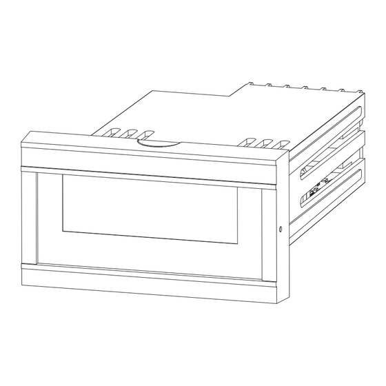
3.2.1 Specifications NOTE: All values are typical, unless otherwise specified. Item Specification Enclosure Rectangular Panel Mounted Meter Material Plastic Size (W x H x D) 89 mm X 41.3 mm X 178 mm (3.5 in. X 1.6 in. X 7.0 in.) Bezel (W x H x D) 112 mm X 62 mm X 17.5 mm (4.41 in. -
Page 10: Dimensions
3.2.2 Dimensions 4.45" (113 mm) 2.45" (62 mm) FRONT VIEW 0.65" (17 mm) 6.2" (158 mm) 1.65" (42 mm) SIDE VIEW PANEL THICKNESS CUTOUT DIMENSIONS (⅛ DIN) 0.1" +0.08 +0.08 3.543" 1.653" (2.7 mm) –0.00 –0.00 0.19" 90 mm 42 mm (5.0 mm) –0 –0... -
Page 11: Wiring Diagrams
3.2.3 Wiring Diagrams 3.2.3.1 Field Wiring Diagram POWER INPUT SERIAL PORT 1 SYNCHRO A B C D TRANSMITTER 1 2 3 4 7 8 9 10 ANALOG RELAY HIGH OUTPUT RELAY COM RELAY LOW PROGRAM ENABLE / DISABLE 3.2.3.2 Field Wiring Diagram with 4–20 mA Output POWER INPUT SERIAL PORT 1... -
Page 12: Field Wiring Diagram - Relay
3.2.3.3 Field Wiring Diagram – Relay SERIAL PORT 1 A B C D 1 2 3 4 7 8 9 10 Source Load Load AC or DC (Lo) (Hi) 3.2.4 Device Functions 3.2.4.1 Terminals Terminal Function Terminal Function Analog Output + Analog Output –... -
Page 13: Dip Switches
3.2.4.2 DIP Switches A DIP switch tells the firmware which hardware options are installed, so their function can be enabled. It is located on the top PCB, above the power transformer and is accessible through a slot in the left side of the case, towards the rear of the instrument (see also §... -
Page 14: Installation
Installation NOTE: • Contact Franklin Electric Technical Support for application assistance if the synchro transmitter and the 1250B monitor are separated by a wire run of more than 1200 feet. • When the installation is complete, make sure this guide is left with the site owner or operator. - Page 15 • The 1250B and the synchro transmitter must be wired to the same AC source. Do not remove the jumpers from terminals E and F. • A provided jumper or keyswitch may be installed between terminals 3 and 4 to prevent the program from being changed.
-
Page 16: Programming
Programming The 1250B has three methods of programming: 1. Numeric Menu 2. Alphanumeric Menu 3. Serial Port Programming Commands • Depending upon the serial port option ordered, the serial programming commands will be either RS-232 ASCII commands or RS-485 packet commands. -
Page 17: Numeric & Alphanumeric Menu Items
Numeric & Alphanumeric Menu Items To access the numeric or alphanumeric programming menu, press the MENU key for several seconds until the display goes blank, then press the SELECT / ENTER key. The display should read “OP 0”. The default menu is the numeric menu. To choose the alphanumeric menu, press the DOWN key to select OP 99. - Page 18 Alphanumeric Default Numeric Protocol Value Programmable Range Function OP 27 S Pt Any valid tap number Segmented Mode: Sets present tap position OP 28 L Pt Any valid tap number Segmented Mode: Loads present tap position into memory OP 29 dSPrL On or OFF Enables display of “r”...
-
Page 19: Serial Port Programming
Serial Port Programming To change a parameter using the RS-232 serial port programming commands, connect a computer terminal to the serial port cable. • The terminal must have the proper Comm port settings to communicate to the 1250B (see § 6.4). •... - Page 20 = Enter (Key) ◊ = Space (Bar) Command Syntax Function Explanation TDELETE◊n Delete data point pair #n from the Will re-number entries in the table N.L. Conversion Table TLEARN ◊yy.yyy Add a learned a data point pair to the Will possibly re-number entries in the table (Learned Non-Linear Conversion Table Degrees, Y= Conversion Value)
-
Page 21: Synchro Noise Filtering
5.3.2 Synchro Noise Filtering There are some applications where the 1250B may be installed in environments where harmonic noise on the power line may cause an unstable reading of the synchro position. Assuming that a stable, steady position reading is always better than a fluctuating reading, INCON®... -
Page 22: Programming
5.3.2.1.1 Programming OP 12 (tnS F) sets the Rotation Rate Threshold for the first filter. If the synchro rotates slower than this number of degrees per second, the measured positions will be accepted as valid synchro positions, and immediately displayed. Synchro rotations faster than this rate will be ignored and assumed to be noise-induced aberrations. -
Page 23: Operating Modes
5.3.4 Operating Modes The 1250B has eight operating modes. Each mode causes the 1250B to function differently. Certain modes will have advantages in certain applications. Determine which of the following operating modes is best suited to your application: Mode # Mode Name Linear Scaled Mode Non-Linear Scaled Mode... -
Page 24: Mode 2 - Non-Linear Scaled Mode
5.3.4.2 Mode 2 – Non-Linear Scaled Mode The 1250B is capable of non-linear conversion / correction. Whenever there are two or more data point pairs in the conversion table, the 1250B will automatically switch to non-linear scaled mode. Conversion table data point pairs may be added manually or “learned”... -
Page 25: Modes 16 & 17 - Base 1 Uni-Polar Segmented
5.3.4.3 Modes 16 & 17 – Base 1 Uni-Polar Segmented These modes are used for LTC monitoring when the lowest tap number is “1”. Multiple neutral taps may be present and can be positioned anywhere between the lowest and highest taps, provided they are grouped together in a single section. To select this operating mode, use the OP 2, Func, MODE command to set the value to “16”... -
Page 26: Modes 18 & 19 - Base 0 Uni-Polar Segmented
5.3.4.4 Modes 18 & 19 – Base 0 Uni-Polar Segmented These modes are used for LTC monitoring when the lowest tap number is “0”. Multiple neutral taps may be present and can be positioned anywhere between the lowest and highest taps, provided they are grouped together in a single section. To select this operating mode, use the OP 2, Func, MODE command to set the value to “18”... -
Page 27: Modes 20 & 21 - Bi-Polar Segmented
5.3.4.5 Modes 20 & 21 – Bi-Polar Segmented These modes are used for LTC monitoring when there is an equal number of raised and lowered taps. Multiple neutral taps may be present and can be positioned anywhere between the lowest and highest taps, provided they are grouped together in a single section. -
Page 28: Programming Notes
5.3.5 Programming Notes If the Degrees Per Tap value is not known, the 1250B can be used to determine this value. Follow these steps to determine the Degrees Per Tap value: 1. Program the 1250B for Linear Scaled Mode as follows: OP 2 Operating mode = 1 OP 3 Counts Per Turn = 360 OP 4 Left Digits = 4... -
Page 29: Options
1250B itself. Check the isolation of all field wiring with respect to earth ground. All wiring should be completely isolated from ground (see § 6.2). Contact Franklin Electric Technical Support for assistance if the problem persists. -
Page 30: Input Isolation Option "-I
Input Isolation Option “-I” The 1250B may be ordered with isolated input terminals. In cases where there is a compromise of the system isolation to earth ground, this option will prevent AC voltage from becoming impressed upon the analog output signal (see note at the end of § 6.1). This option consists of two small signal isolation transformers installed in the signal input circuitry. -
Page 31: Serial Rs-232
Serial RS-232 The Serial RS-232 (DCE) option on the Model 1250B can be used to program the instrument or to retrieve position data from the instrument. A Null Modem Adaptor is not needed with the provided serial cable. There are seven operating modes for the serial RS-232 port: 1. -
Page 32: Serial Rs-485 Multi-Drop Option "-M
Communication Port Settings Baud rate, word length, parity, stop bits, and address are programmable using the OP 80, Port, PORT command. See § 5.2 and § 5.3.1 for command protocol and choices. NOTE: When the port is programmed for 2 Stop Bits, the Parity must be “NONE”. Wiring: Digital Communication Connector Pin-Out 1250B DB-9... -
Page 33: Rs-485 Packet Format - Write
Read Registers Command Format Read Registers Response Format GAP 3.5 Char Min. GAP 3.5 Char Min. Device Address 80h Device Address 80h Function Code 03h Function Code 03h # of First Register Hi 01h Byte Count 08h # of First Register Lo 03h Data from First Register Hi 01h # of Registers to Read Hi 00h Data from First Register Lo 03h... -
Page 34: Rs-485 Packet Format - Error Exception Response
6.5.3 RS-485 Packet Format – Error Exception Response When the primary sends a command, the MSB bit in the Function Code is always clear. When a secondary responds to the command, the secondary leaves the MSB bit in the Function Code clear if the response is a normal response and sets MSB bit on if the response is an error exception response. -
Page 35: Rs-485 Modbus Register Definitions Table
Format This column defines what a register contains bit-by-bit in binary. A row of 16 symbols shows what each of the 16 bits of the register contain MSB first and LSB last. A BCD formatted floating point register is shown as follows (two 16 bit binary words): Bcdabcdbbcdcbcdd bcde000000vspppp •... - Page 36 RS-485 MODBUS Register Definitions Register Function Binary Format 40264 0107 tap, neutral tttttttt0000nnnn “0000” are unused bits Read Only t = Tap Number n = Neutral Number Signed Integer, Two’s Complement 40513 0200 draghand reset control 00000000000000HL bit = 1 to reset Read/Write H = High Draghand L = Low Draghand...
- Page 37 RS-485 MODBUS Register Definitions Register Function Binary Format 44615 1206 relay high tap ssssssssssssssss 16 bits, high tap limit Read/Write 44616, 44617 1207, 1208 rotation rate filter threshold bcdabcdbbcdcbcdd bcde000000vspppp Read/Write 44618, 44619 1209, 120A averaging filter threshold bcdabcdbbcdcbcdd bcde000000vspppp Read/Write 44620, 44621 120B, 120C...
- Page 38 RS-485 MODBUS Register Definitions Register Function Binary Format 45889 1700 table add/del/edit control 0000000000000ccc 3 LSBs (ccc) select: Read/Write 000 = No Operation 001 = Clear Table 010 = Add to Table * 011 = Load Table Position ** 100 = Delete Table Position ** 101 = Add Learned Table Position * 45890 1701...
-
Page 39: Field Calibration And Test
Field Calibration and Test Calibration The 1250B should not require field calibration. However, there are provisions in the menu to facilitate Analog Output Calibration. The analog output may be adjusted in the field. A calibrated multi-meter should be used to measure the output signal during calibration. -
Page 40: Self-Diagnostic Tests
Self-Diagnostic Tests The 1250B regularly performs several self-check diagnostic tests and generates error codes in the form “FA n” and “ERR n” if it detects an internal fault. The “n” number indicates the type of failure detected. See § 8 for a full list of error codes and their descriptions. -
Page 41: Error Codes
Error Codes Display Description FA 2 Watchdog Re-start (Processor Crash) – If the condition recurs, call Technical Service. FA 3 Memory Error at Startup – User programming is erased; Factory program defaults are re-loaded. FA 5 Keyboard Error at Startup – Up, Down Key, or more than one key is being pressed during Power-Up. -
Page 42: Appendix
Appendix Related Documents Documentation can be found online at www.franklingrid.com. Part Number Description 000-1077 1250B Install & Programming Guide 000-1371 Synchro Coupling & Mount Dimensional Reference Guide 000-2045 Retrieving Tap Change Indication Data from a 1250B 000-2060 Interfacing the 1250B / 1250LTC / 1511-LTC Monitors TBGS1222-01 FA25 Error Code On 1250 Display... -
Page 43: Notes
Notes... - Page 44 GRID SOLUTIONS 000-1077 r11 December 18, 2024...
Need help?
Do you have a question about the INCON 1250B and is the answer not in the manual?
Questions and answers