
Related Manuals for RS Flight Systems iS Control Panel C24

Summary of Contents for RS Flight Systems iS Control Panel C24
- Page 1 Operation Manual iS Control Panel C24 iS Control Panel C24 Remote Portable Test Bench C24 Portabel Test Bench C24 Remote Version: 1.0 © Copyright 2024 RS Flight Systems GmbH...
-
Page 2: Table Of Contents
Contents Preface .............................3 System Description ..........................3 Technical Specifications ........................4 Electrical Installation ........................6 Operation ............................10 26.08.2024 | V1.0 Operation Manual iS Control Panel C24... -
Page 3: Preface
EMU IOM. System Description The iS Control Panel C24 (iSCP C24) can operate BRP Rotax engines of the iS series. Commonly it is used for first operation and trouble shooting. The iSCP C24 replaces the complete airframe wiring and gets connected to the engine with four connectors and two terminal clamps. -
Page 4: Technical Specifications
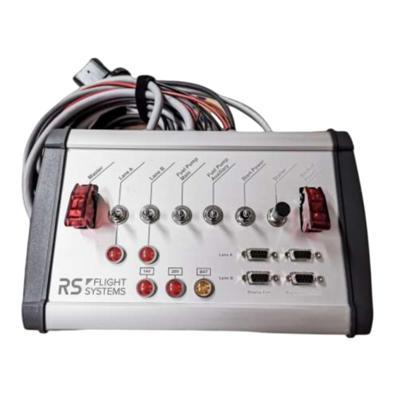
Integrated power PCB Operating -20 to +70 Temperature Range -4 to +158 Humidity < 95 %, non-condensing Table 3-1: Technical Specification iS Control Panel C24 Figure 3-1: iS Control Panel C24 (isometric view) 26.08.2024 | V1.0 Operation Manual iS Control Panel C24... - Page 5 Figure 3-2: iS Control Panel C24 (top view) Operation Manual 26.08.2024 | V1.0 iS Control Panel C24...
-
Page 6: Electrical Installation
HIC A, HIC B, X2 and X5 are mating connectors for the BRP Rotax engine harness. The Power input is equipped with 3 terminal clamps. The wiring output is shown in Figure 4-1. Figure 4-1: iS Control Panel C24 (back view) The pinout of the HIC A, HIC B, X2 and X5 connectors is described in the following tables. - Page 7 Signal Name Signal Description Airframe PWR Aircraft Battery Supply BLACK Airframe GND Aircraft Battery GND Table 4-5: Terminal Clamps out The pinout of the 4 DSUB connectors is described in Table 4-6. Operation Manual 26.08.2024 | V1.0 iS Control Panel C24...
- Page 8 All functions which are sketched outside the scope certification line (double-dotted line) are integrated in the iSCP C24. Note: There is no switch function on the iSCP C24 for the AUX fuel pump. 26.08.2024 | V1.0 Operation Manual iS Control Panel C24...
- Page 9 Figure 4-2: Wiring diagram Rotax 915iS C24 Operation Manual 26.08.2024 | V1.0 iS Control Panel C24...
-
Page 10: Operation
Activate the master switch of the iSCP C24. If you have connected an EMU to the Display Port, this device will be powered up now. For starting the engine with the iSCP C24, please refer to the Operators Manual of the BRP Rotax 915iS C24. 26.08.2024 | V1.0 Operation Manual -10- iS Control Panel C24... - Page 12 RS Flight Systems GmbH Oberer Luessbach 29-31 82335 Berg | Germany +49 8178 8681 – 300 contact@rs-flightsystems.com www.rs-flightsystems.com iSCP C24 | Version: 1.0 © Copyright 2024 RS Flight Systems GmbH...
Need help?
Do you have a question about the iS Control Panel C24 and is the answer not in the manual?
Questions and answers