Table of Contents
Advertisement
Quick Links
INSTALLATION GUIDE
V1.2
Issue Date: 2024-10-16
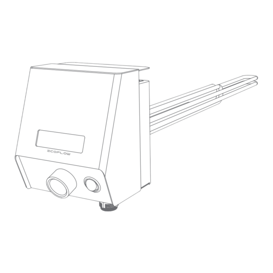
ECOFLOW POWERGLOW
Smar t Immersion Heater
For the latest documents, please scan the QR code or visit:
https://enterprise.ecoflow.com/eu/documentation
IMPORTANT
• Before installing, operating, and maintaining the equipment, read and
follow up Installation Guide and Safety Instructions.
Advertisement
Table of Contents

Subscribe to Our Youtube Channel
Related Manuals for EcoFlow POWERGLOW

Summary of Contents for EcoFlow POWERGLOW
- Page 1 INSTALLATION GUIDE V1.2 Issue Date: 2024-10-16 ECOFLOW POWERGLOW Smar t Immersion Heater For the latest documents, please scan the QR code or visit: https://enterprise.ecoflow.com/eu/documentation IMPORTANT • Before installing, operating, and maintaining the equipment, read and follow up Installation Guide and Safety Instructions.
-
Page 2: Table Of Contents
2 Preparing Tools and Instruments 2 What's In The Box 3 System Installation Installation Environment Requirements Installation Space Requirements Mounting EcoFlow PowerGlow to Water Tank 5 Electrical Connection Integrating EcoFlow PowerGlow to EcoFlow PowerOcean System Integrating EcoFlow PowerGlow to Third-... -
Page 3: Statement
Caution, risk of electric shock. under the warranty. EcoFlow will not be liable for any consequences of the following Indicates a hazard with a medium level WARNING of risk which, if not avoided, could circumstances: result in death or serious injury. -
Page 4: Preparing Tools And Instruments
×6 Tubular Terminal AC IN connector Wi-Fi Antenna (For wire gauge 0.5 mm²) ×5 ×1 × 1 Tubular Terminal Feed-Through Terminal Block EcoFlow PowerGlow Smart Immersion Heater NTC with cable (2 m) (For wire gauge 1.5 mm²) (For EF RD-P1-3K5-S1 only) -
Page 5: System Installation
• A permanent earthing of the water tank that the EcoFlow PowerGlow mounted to is mandatory. • The water tank that the EcoFlow PowerGlow mounted needs to be configured with a pressure- relief device, which is to be connected to a discharge pipe with a steady downward inclination in a frost-free environment. -
Page 6: Installation Space Requirements
3.5kW: >375mm 6kW: >550mm 9kW: >550mm WARNING • The hot water storage tank must be drained before installing EcoFlow Mounting EcoFlow PowerGlow. PowerGlow to Water Tank • The threaded socket must be shorter than the unheated zone of the heating rod. -
Page 7: Electrical Connection
Communication with the EcoFlow PowerOcean system takes place via RS485 or accessing the same wireless network (Wi-Fi). When connected with the PowerOcean system, the EcoFlow PowerGlow will be powered by PV excess and utility grid, implementing intelligent scheduling of energy use via EcoFlow App. Effortlessly manage, monitor, and control your devices through a sleek, user-friendly interface via app or web management. -
Page 8: Three-Phase Wiring Diagram
Smart meter communication cable 0.2mm² to 0.5 mm² 0.2mm² to 0.5 mm² NOTICE • Wiring may vary based on the regulation requirements of different regions. Refer to Three-Phase Wiring the specific requirements of local regulations. Diagram Integrating EcoFlow PowerGlow to EcoFlow PowerOcean System... -
Page 9: Single-Phase Wiring Diagram
Integrating EcoFlow PowerGlow to Third-Party PV system NOTICE • Wiring may vary based on the regulation requirements of different regions. Refer to Single-Phase Wiring the specific requirements of local regulations. Diagram Integrating EcoFlow PowerGlow to EcoFlow PowerOcean System Using Three-Phase RCD... - Page 10 Using Single-Phase RCD Integrating EcoFlow PowerGlow to Third-Party PV system Using Three-Phase RCD...
-
Page 11: Connecting Ac In Cables
Using Single-Phase RCD NOTICE Connecting • Ensure that all cables are connected correctly and securely. AC IN Cables ❶ ❷ 5× 5× NOTICE ❶ L1, L2, L3, N, PE refer to ❷ the wiring pole close to respectively and accordingly. -
Page 12: Optional) Establish Communication Connection With Ecoflow Powerocean
Network cable Method 2: Wireless Connection (Wi-Fi) To access the same wireless network, visit the EcoFlow App, then go to PowerOcean Device Settings to add device on system component page. For details about adding device to PowerOcean system, refer to the installation guide that comes with the PowerOcean. -
Page 13: Connecting Smart Meter
Find the home mains and connect the smart meter as shown in the diagram. Load L3 10 Load N METER COMMUNICATION Find communication port 24,25 on the meter and connect them to the RS485 port of EcoFlow PowerGlow. 24 RS485A 25 RS485B 10 Grid N Grid L3... -
Page 14: Connecting To Network
NOTICE Connecting to • Use shielded CAT 5 or higher rating network cable for stable connection. Network ·METHOD 1: VIA A WIRED NETWORK ❶ ❷ RJ45 Connector RJ45 Connector Both ends of the network cable use the T568B wiring standard. T568B T568B 10-20 mm... -
Page 15: Connecting Ntc
Connecting NTC TEMP SENSOR ❶ ❷ Installing Wi-Fi Antenna Securing the Control Panel ❷ ❷ Screwdriver (PH3) ❶... -
Page 16: System Commissioning
NOTICE • If the LCD indicates a faulty status, visit the NOTICE EcoFlow app to retrieve the error code for troubleshooting. • During the initial commissioning, you need to press the knob once or send a power-on command via EcoFlow app to activate the heating mode of the device. -
Page 17: App Control
Control 1. DOWN AND INSTALL ECOFLOW USER APP Scan the QR code or download at: https://download.ecoflow.com/app EcoFlow App 2. CREATE NEW ACCOUNT AND LOG IN. 3. ADD DEVICE. 4. CONNECT TO INTERNET VIA WIFI OR ETHERNET. - Page 18 © 2024 EcoFlow Inc. All rights reserved. 16 |...
Need help?
Do you have a question about the POWERGLOW and is the answer not in the manual?
Questions and answers