Advertisement
Quick Links
MCC3721NC Laser Cutting Installation Guide V2.0
AU3TECH RESEARCH PTY LTD
Email: info@au3tech.com
Web: www.au3tech.com
1. Product Overview
MCC3721NCLaser cutting control card is for fiber laser cuttingThe new generation CNC
system developed in the field has abundant peripheral resources and powerful functions.
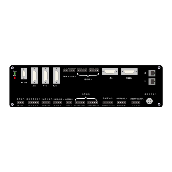
2. Schematic diagram of MCC3721NC control board
Description of each port
Port name
power input +24V
Electric
focusing
head
interface
Axis limit
input
1
Wuhan Au3tech Intelligent Technologies Co., Ltd.
effect
DC24V input positive
PG
Protective grounding
0V
DC input negative, power ground.
24V
DC24V output, used to power the
electric head
0V
DC input negative, power ground.
B
Communication interface, docking
with port B of electric head
G
Communication signal ground
A
Communication interface, docking
with port A of electric head
X+
X-axis positive limit input,
dedicated signal, active low
Remarks
It is recommended to
use 24V/≥10A DC
power supply
This port is only
used to control the
electric cutting head
of Au3tech
X-axis limit/origin
input
Advertisement

Summary of Contents for Au3Tech MCC3721NC
- Page 1 1. Product Overview MCC3721NCLaser cutting control card is for fiber laser cuttingThe new generation CNC system developed in the field has abundant peripheral resources and powerful functions. 2. Schematic diagram of MCC3721NC control board Description of each port Port name...
- Page 2 Wuhan Au3tech Intelligent Technologies Co., Ltd. X-axis origin signal, dedicated signal, active low X-axis negative limit input, dedicated signal, active low Ground, the common terminal of X- axis limit signal. Y-axis positive limit input, Y-axis limit/origin dedicated signal, active low...
- Page 3 Wuhan Au3tech Intelligent Technologies Co., Ltd. in single drive mode, this port isY1 axis(Alternate) Control port. Fourth The fourth axis control signal. It can be used to axis control the exchange platform/automatic coil/third-party electric head. Universal The first general output port...
- Page 4 Wuhan Au3tech Intelligent Technologies Co., Ltd. default low level is active The 5th general input port, the default low level is active Input signal common The 6th general input port, the default low level is active The 7th general input port, the...
- Page 5 The laser can be connected to the system through various methods such as network port, RS232 port and I/O port. 3.2 Installation dimensions MCC3721NC control card supports 35mm rail installation, length (330mm) X width (120mm) X height (50mm) 330mm 3.3 Installation limit/other IO ports...
- Page 6 The typical wiring of mechanical limit switch is as follows: General passive output: The MCC3721NC CNC card provides 8 universal custom output port, the output port function can be freely configured through software. It can control relay coils, signal lights, etc. It is not recommended to connect solenoid valves and other peripherals with higher rated power to this port.
- Page 7 The output method is shown in the figure below: 3.4 Connect XY axis servo drive The MCC3721NC control card provides 5 servo control interfaces, namely X axis, Y1 axis, Y2 axis, Z axis, and fourth axis. Where the Z axis is The height controller controls the axis.
- Page 8 DIR+ DIR- The MCC3721NC control card adopts "pulse + direction signal" to control the servo drive, which can support various servo drives such as Yaskawa, Panasonic, Fuji, Delta, Inovance, Zhongweixing, etc. Our company can provide corresponding brand servo drive control according to user needs.
- Page 9 Wuhan Au3tech Intelligent Technologies Co., Ltd. The basic parameter settings of Yaskawa ∑—ⅴ series are as follows: parameter Settings meaning Pn000 001X Set the servo control mode to position mode Pn00B default Change to 0100 for single-phase power input Pn200...
- Page 10 Wuhan Au3tech Intelligent Technologies Co., Ltd. Fuji A5 series basic parameter settings parameter Settings meaning PA-101 Set the servo control mode to position mode PA-103 Set "pulse + direction" mode SchneiderLexium-23D-CNSeries wiring diagram...
- Page 11 Wuhan Au3tech Intelligent Technologies Co., Ltd. SchneiderLexium-23D-CNSeries basic parameter setting parameter Settings meaning name P1-00 0100 Set pulse method P1-01 0000 Location mode P2-00 Factory value Position control proportional gain, real-time adjustment according to actual situation P2-10 Make DI1 function plan as servo enable...
- Page 12 Wuhan Au3tech Intelligent Technologies Co., Ltd. Inovance IS620P series basic parameter settings parameter Settings meaning name H02-00 1—Location mode Mode selection H02-02 0—Forward mode Rotation direction selection H02-03 0—Forward mode Output pulse feedback direction selection H03-08 2—Fault reset DI4 terminal function selection H03-10 1—Servo enable...
- Page 13 Wuhan Au3tech Intelligent Technologies Co., Ltd. Fuji A5-SMART-PLUS wiring diagram Fuji A5-SMART-PLU parameters parameter Reference meaning name P1-01 Location mode P1-03 Command pulse/command symbol P1-05 10000 Every rotation1 Number of command input pulses per week P1-08 2500 Every rotation1 Number of output pulses per week Note: The following parameters need to be adjusted in real time according to actual usage.
- Page 14 Self-tuning gain2 value 4 3.5 Connect the laser The MCC3721NC numerical control board can be connected to the laser through the computer serial port/network port, and it can also be connected to the laser through the I/O port signal. The Raycus laser can be directly connected to the computer serial port, and the IPG laser can be connected to the IO port/network port.
- Page 15 Wuhan Au3tech Intelligent Technologies Co., Ltd. Note: The analog input voltage required by the IPG-YLR laser is 0-4V and can be configured by numerical control software. The 5V modulation signal can be changed to the 5V terminal through the jumper cap of the board; the 5V voltage input of the laser red light and enable is required Connect a 5V switching power supply to the COM port of the CNC board.
- Page 16 10m or 15m signal transmission line provided by us (interface type: M12-4 aviation plug). 3.7 Connect to computer The MCC3721NC control card can be directly connected to a computer (industrial computer) through any network port, which is convenient and quick. 3.8 Installing the power supply When all the other peripherals are connected, 24V power supply is required for the CNC board.
- Page 17 Wuhan Au3tech Intelligent Technologies Co., Ltd. 1. Set the IP address of the host computer. Can be quickly set through the software. After opening the software, select "Advanced" —> "Set Local IP". Because the WINDOWS system used by some customers does not open the function of automatically setting the local IP, The user can also manually set the computer host IP address: 10.1.1.10, subnet mask:...
- Page 18 Wuhan Au3tech Intelligent Technologies Co., Ltd. Parameter configuration is mainly used to configure the basic parameters of core components such as machine tools, lasers, height controllers, and gas. The user should carefully configure the parameters to avoid errors during operation.
- Page 19 Wuhan Au3tech Intelligent Technologies Co., Ltd. Calculation formula: pulse needs to calculate it by equivalent=Number of pulses combining the number of per revolution/XShaft pitch pulses per revolution of the drive or the electronic gear ratio and the running pitch of the machine tool...
- Page 20 Wuhan Au3tech Intelligent Technologies Co., Ltd. Double drive Set the number of double- Only when two conditions are tolerance drive error pulses met at the same time can the dual drive error alarm be triggered Double drive Set the duration after...
- Page 21 Wuhan Au3tech Intelligent Technologies Co., Ltd. Return distance Return distance after (mm) completion Configuration steps: 1. Choose X, Y drive mode (single drive/double drive) according to the machine tool structure. If the Y-axis of the machine tool is in single-drive mode, the user should cancel the Y- axis bilateral drive option.
- Page 22 Wuhan Au3tech Intelligent Technologies Co., Ltd. The system defaults to two times of returning to the original. Users can freely configure the origin signal. Support the use of servo motor Z phase/limit/origin signal as the origin sampling signal. The user can set the corresponding back-to-origin parameters according to the above figure.
- Page 23 Whether the light and the laser are normal. 4.3.3 Height controller configuration and debugging The MCC3721NC numerical control board integrates the Z-axis capacitance height controller, and uses "pulse + direction signal" to control the servo drive. The definition and wiring of the Z-axis port can refer to the X/Y axis. In the parameter...
- Page 24 If the information is displayed normally, it indicates that the MCC3721 onboard capacitor height controller has been configured successfully. 4.3.4 Electric focusing head configuration When MCC3721NC is matched with Osendike electric focusing head, select the onboard serial port option.
- Page 25 Wuhan Au3tech Intelligent Technologies Co., Ltd. If the user configures a third-party electric head, you need to enable the expansion board first, and then select the fourth axis control on the electric focusing interface. Electric focus parameter selection fourth axis control F rom syst em a naly sis —E lect ric focu s en ter the four th a xis elect ric focu s...
- Page 26 Wuhan Au3tech Intelligent Technologies Co., Ltd. 4.3.5 Gas configuration and debugging The system supports two gas control methods: high and low pressure valve/proportional valve. The corresponding gas port can be configured as required.
- Page 27 Wuhan Au3tech Intelligent Technologies Co., Ltd. Description: The air pressure correction only supports the gas configured as a proportional valve. By setting the number of air pressure correction points and the voltage of each point and the corresponding air pressure value, accurate air pressure control is ensured.
-
Page 28: Trial Run
Wuhan Au3tech Intelligent Technologies Co., Ltd. 2. Press the left and right buttons of the handle at the same time to complete the pairing. 5. Trial run After the components are configured, the trial operation can be started. The user can confirm according to the following steps: 1. - Page 29 Wuhan Au3tech Intelligent Technologies Co., Ltd. 3. Confirm that the height controller works normally. When the system works for the first time, be sure to perform float calibration. Please ensure the following content in order for calibration: ⚫ Directly below the cutting headPlacedSheet metal to be calibrated ⚫...
- Page 30 Wuhan Au3tech Intelligent Technologies Co., Ltd. Note: The origin fine adjustment function is used to correct the zero position of the electric focusing window. Generally, no user adjustment is required. 5. Confirm whether the laser/gas is working properly. Step 1: Set the gas type, gas delay, laser burst power, frequency and other parameters in the operating parameters.
- Page 31 Wuhan Au3tech Intelligent Technologies Co., Ltd. So far the system configuration is complete. As the software version is constantly updated and iterated, the functions and parameter interfaces are subject to the actual software; if there are differences or omissions, please contact the relevant after-sales technical support personnel, or pay attention to the latest version released on the official website.
Need help?
Do you have a question about the MCC3721NC and is the answer not in the manual?
Questions and answers