
Summary of Contents for Meyer Burger MB BF6B1B 17
- Page 1 Installation and operating instructions Valid for the following Meyer Burger solar roof tile: MEYER BURGER TILE - Product type: MB_BF6B1B_17...
-
Page 2: Table Of Contents
Contents 1. Introduction 1.1 Certification and technical data 1.2 Scope of application 1.3 General information 1.4 Intended use 2. Planning 2.1 Electrical design 2.2 Series connection 2.3 Parallel connection 3. Mounting 3.1 The Meyer Burger Tile roof system 3.2 Module alignment 3.3 Place of installation 3.4 Transportation 3.5 Security 4. Installation instructions 4.1 Example roof construction 4.2 Mounting 4.3 Electrical installation 4.4 Commissioning 4.5 Security 4.6 General information... -
Page 3: Eu-Standards
During the planning, installation, operation and maintenance of grid-connected The following regulations and standards, among others, must be observed for photovoltaic systems: EU-STANDARDS NATIONAL STANDARDS EUROCODE 1 (EN 1991-1) German Institute for Building Technology Building Rules List B Part 1 EN 13501 Model administrative regulation for Behavior of building materials and components in the event of technical building regulations fire DIN EN ISO 7441:2015 EN 60728-11 Corrosion of metals Installation and operation (earthing) of antenna systems... -
Page 4: Introduction
1. Introduction Congratulations on the purchase of your Meyer Burger The patented movability of the glass pack offers a number of Tile solar roof tile advantages for the application of Meyer Burger Tile. The roofer installs the Meyer Burger Tile in the same way as The Meyer Burger Tile was developed and designed in conventional roof tiles. The electrician then connects the Germany and Switzerland and manufactured in Europe. When electrically interconnected Meyer Burger Tile to the inverter. selecting all components for the solar roof tile, we attached In combination with our fastening concept, it is also possible great importance to efficiency, quality and durability. to simply remove any Meyer Burger Tile at any point without having to completely or partially remove and re-roof the entire The most important properties are as follows: roof. • Simple assembly • E asy to replace • V ery high durability • E xtremely high protection against hail, wind and snow loads •... -
Page 5: Certification And Technical Data
1.1 Certification and technical Data For a further list of currently available certificates and all technical and electrical data, please refer to the corresponding data sheets at www.meyerburger.com. The modules are tested and approved in accordance with IEC 61215-2021 and IEC 61730-2016. Module line Meyer Burger Tile Fire class according to Hard roofing B (t1) ROOF EN 13501-5 Solar cell type Half-cell module M6, mono n-Si, HJT Hail resistance class accor- HW 5 Front cover Solar glass, 3.2 mm ding to VKF Back cover Float glass, 3.0 mm Meyer Burger Tile/m Dimensions L x W x H [mm] 521.2 x 334.0 x 26.3 Power/m 167 W/m Visible area [m 0.10 Deck length3 (recommended) 340 mm Weight [kg] Deck width 300 mm Design load +/- [Pa] 6,000 / 1,600 Distance between Meyer > 1 mm Max. Test load +/- [Pa] 9,000 / 2,400 Burger Tile... -
Page 6: Scope Of Application
1.2 Area of application 1.4 Intended use The modules are suitable for the following areas of These installation instructions are valid in Europe. The application: instructions provide information on safety when handling • Ambient operating temperature -40 °C to +45 °C. the crystalline high-performance solar roof tiles from Meyer • C ompressive loads of max. 9,000 Pa (corresponding to Burger (Germany) GmbH as well as on installation, mounting, approx. 920 kg/m2 ) and tensile loads of max. 2,400 Pa wiring, maintenance and recycling. (corresponding to approx. 240 kg/m2 ) (including safety factor 1.5) . NOTE • I nstallation is carried out on a substructure for roof tiles in accordance with the regulations of the German roofing Deviations from the installation instructions and changes to the solar roof tile will invalidate the guarantee and trade. -
Page 7: Planning
2. Planning The Meyer Burger Tile uses highly efficient HJT solar cells with 2.2 Series connection the patented SmartWire Connection Technology (SWCT®). • The modules can be connected in series to achieve the re- These are optimally arranged so that they achieve a high quired total voltage. power density with appealing aesthetics. • The current (current at the max. power point, I ) of the modules connected in series should be the same, as the maximum current is determined by the module with the 2.1 Electrical Design lowest current. • The Meyer Burger Tiles have pre-installed bypass diodes • T he maximum system voltage must be observed and can (not replaceable), which ensure protection and improved be found in the table in the chapter "Technical data - Max. performance of the overall system if one or more Meyer system voltage" or in the corresponding data sheet. System Burger Tiles are shaded. voltage" or the corresponding data sheet. • Only modules of the same module line and power class • T he maximum number of modules in series is calculated by may be interconnected. dividing the maximum system voltage (Usys) by 1.25 times •... -
Page 8: Mounting
3. Mounting 3.1 The Meyer Burger Tile- roof system Despite these properties, it is not recommended to unpack The Meyer Burger Tile system consists of a Meyer Burger Tile, them before starting the roofing work to avoid accidental the complementary roof tiles and the following components, damage to the Meyer Burger Tile. The storage environment which must be provided by the installer on site: must be dry and protected to prevent damage to the product • Eaves plate below and packaging. • Perforated plate below • Cable for connecting the rows (pre-assembled) We recommend recycling the packaging of the supplied Meyer • T op ridge plates Burger Tile. Please contact your local waste disposal company. • M etal sheets for complementary gable ends Proceed with caution when unpacking, transporting or storing and observe the following instructions: 3.2 Module alignment • During storage and transportation, the Meyer Burger Tile •... - Page 9 • The housing must not be modified or attached in any way other than described in the instructions. Strictly adhere to the installation instructions. Appropriate safety precautions must be taken when working • Do not hold or transport the Meyer Burger Tile by the on roofs. The safety regulations of the trade association must cables. be strictly observed. To protect yourself and Meyer Burger • O bserve the safety instructions for the other components Tile, the following safety instructions must be observed: of the solar system. • When installing and maintaining the Meyer Burger Tile, • O pening a closed string (e.g. when disconnecting the DC follow the guidelines and safety instructions for installation from the inverter under load) can cause a life-threatening and maintenance.of electrical appliances and/or systems arc: as well as the guidelines for grid-parallel operation of solar - Do not disconnect the Meyer Burger Tile under load or systems from the energy supplier must be observed. volta • B efore installation, each Meyer Burger Tile must be inspec- - Only Meyer Burger Tiles in voltage-free strands may be ted and checked for mechanical integrity (e.g. glass break- disconnected at the plug using a suitable tool age). Do not install a damaged Meyer Burger Tile. • Every component of the Meyer Burger Tile System is made •...
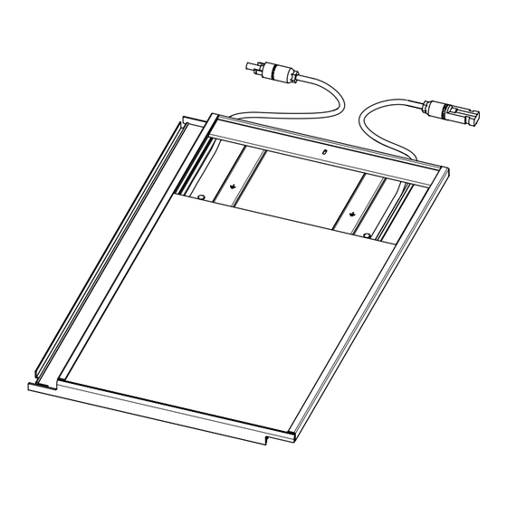
- Page 10 Structure of the Meyer Burger Tile Two cables with a plug and a socket are led out from the top The Meyer Burger Tile consists of two different parts. One of end of the housing. These are used for the horizontal con- these is the photovoltaic module (PV module), which consists nection between the individual Meyer Burger Tile. Due to the of two glass panes that form a permanent unit together with different connectors, there is always a Protection against re- the solar cells and the encapsulation material. On the back verse polarity guaranteed. Further, more detailed information of the PV module is the junction box with the bypass diode, on this topic and notes for planning can be found in chapter 5 the two cables and the two plugs. The finished PV module is "Planning notes". pushed into the mounting housing, which is then screwed into place. The resulting product is the Meyer Burger Tile, which is Only connectors of the same type as the Meyer delivered ready for installation. Burger Tile may be used for installation. The plug connector of the Meyer Burger Tile may differ Fastening the Meyer Burger Tile to the roof structure from the plug connector of the inverter. The Once the Meyer Burger Tile has been positioned horizontally same connector types (see information in the on the support battens, it must be fastened to the support data sheet and on the Meyer Burger Tile) must battens with two sheet metal screws (see technical data for be used to connect the strings. specifications) (see Figure 4). The module can only be safe- ly accessed by the roofer or electrician and used as a step If this is not possible, an adapter cable with the aid once it has been screwed to the substructure (support original Meyer Burger Tile connector and the battens). selected string connector can be used. Electrical connection of the Meyer Burger Tile Solar plug for simple and safe elect- rical assembly High-performance module with HJT solar cells and SmartWire Connection Technology Roof batten...
- Page 11 Rear ventilation of Meyer Burger Tile In order to enable rear ventilation for better cooling of the mo- dule despite the closed housing under the Meyer Burger Tile, the housing is open at the bottom end and open at the top end. By placing the Meyer Burger Tiles on top of each other, there are always two openings above each other and a continuous air duct is created. This favors the creation of a chimney effect, which ensures cooling of the modules on the rear side. Figure 5 shows overlapping Meyer Burger Tiles. In order to ensure the rear ventilation of the Meyer Burger Tiles when installed, it must be ensured that a sufficient ventilation cross-section is available on site at the beginning and end of each tile gap (min. 46 cm2 ). This can be achieved using ventilation gril- les, ventilation roof tiles or ventilation ridges, for example. Figure 5: Air duct in the housing of the Meyer Burger Tile...
-
Page 12: Installation Instructions
IMPORTANT! When planning, the greater overall length of planning. This coordinated planning must be precisely marked the Meyer Burger Tile housing must be taken into account on the installation plan and/or roof plan. Before starting the in order to provide sufficient space in the ridge area. Com- installation work, these connections should be checked again pared to most complementary tiles (length 420 mm), the on site. - Page 13 4.2 Installation of the Meyer Burger Tile To ensure this rear ventilation, there must be a ventilation The distance between the eaves board and the lower edge of opening at the bottom (eaves area) and at the top (ridge area) the rafters is shown in the table below. On the one hand, this (ventilation and extraction). The ventilation cross-section must position provides ideal mechanical support for the roof tiles. not be less than 46 cm2. On the other hand, it ensures that the opening for the air duct of the Meyer Burger Tile is sufficiently large so that sufficient air can flow behind the solar roof tiles for rear ventilation. Roof angle 35° – 70° V [mm] min. 90 W [mm] X [mm] Z [mm] Figure 7: Profile view with dimensions for mounting on a roof with ridge...
- Page 14 Figure 8: Positioning the eaves flashing on the eaves beam Figure 10: Positioning and screwing of the perforated plate Figure 9: Screwing the eaves plate to the eaves beam After installing the eaves batten, the eaves flashings are posi- tioned and screwed together as shown in Figures 8 and 9. If several flashings are required for the entire roof, they must over- lap by at least 250 mm. All overlapping eaves flashings must be connected in such a way that they are electrically conductive. Figure 11: Positioning and screwing of another perforated plate This ensures that the necessary electrical potential equalization takes place via these sheets. As shown in Figure 12, there are two aluminum round bolts in the upper area of the Meyer Burger Tile, which serve to hold The perforated sheet is then attached to the flashing and the the Meyer Burger Tile on the roof battens. eaves board. Several perforated sheets are placed next to each other and screwed to the eaves board, as shown in Figure 11. After positioning the Meyer Burger Tile, it must be fastened to The perforated sheet serves to protect animals from crawling in. the support battens with two sheet metal screws (see technical data for specifications), as shown in Figure 12. The module is The roof covering starts in the bottom right-hand corner. The only accessible to the installer once it has been screwed onto Meyer Burger Tile is laid to the left of the complementary roof the support battens. tile.
- Page 15 Detail of fixing Retaining bolt Figure 14: Start of the roofing in the bottom right corner of the roof with a Meyer Burger Tile Figure 12: Positioning the Meyer Burger Tile on the roof battens Meyer Burger Tiles are laid along the eaves until the desired quantity is reached, as can be seen in Figure 15. Figure 13: Covering the second row with the Meyer Burger Tile Figure 15: Roofed eaves row with gable-side roof tile and the additional tiles to the left and right When positioning the next Meyer Burger Tile on of the Meyer Burger Tile. the batten, a horizontal distance of at least 1.0 Once the first row has been positioned, the second row fol- mm must be maintained between the individual lows the same procedure as before by mounting and securing Meyer Burger Tiles to avoid thermal stresses. the Meyer Burger Tile to the support battens as shown in Figure 16. Local specifications for fixing the roof tiles must be observed.
- Page 16 The roofing continues in this way up to the last row on the roof After installing the ridge sheets on the left and right side, the ridge. The ridge system is installed after all the roof tiles have ridge cap (curved) is placed on the roof peak and screwed into been covered and the Meyer Burger Tile has been electrically the ridge batten holders using self-sealing screws. connected. Ridge batten holders are used to mount the ridge sheets. The ridge sheets must be installed in such a way Ridge batten holder Ridge cap (curved) that shading is avoided. Ridge plate (left) Ridge plate (right) Adapted Rafters Figure 16: Covering the second row with the Meyer Burger Tile Figure 18: Ridge batten holder with installation of the ridge plates Figure 17: Covering the entire roof...
-
Page 17: Electrical Installation
4.3 Electrical Installation The electrical installation includes the following points: which a self-drilling screw (see technical data for specificati- ons) is screwed in completely. This connects the Meyer Burger • Screwing of the Meyer Burger Tile to the supporting bat- Tiles in the eaves area electrically to the eaves sheet. tens by the roofer The eaves flashing must be integrated into the existing equi- • Electrical connection of the individual modules and potential bonding of the building. connection to the inverter • Establishing equipotential bonding between the individual This step must be carried out for all Meyer Burger Tiles at modules the eaves. The electrical connection of the solar roof is then • Establish equipotential bonding by screwing the Meyer started in the first column. Burger Tiles to the eaves with the eaves plate using two screws The electrical connection of the individual Meyer Burger Tile also starts in the eaves. The electrical connection is made Electrical connection of the Meyer Burger Tile horizontally in a row between the adjacent Meyer Burger Tiles. The electrical installation of the Meyer Burger Tile should start in the eaves area. To do this, the PV module in the Meyer The two plugs of the adjacent modules must be connected to Burger Tile is pushed up the eaves. The two potential equali- each other. A proper connection is established when the plugs zation lugs and the eaves plate under the Meyer Burger Tile click audibly into place (slight clicking sound). The poten- become visible. tial equalization between the two Meyer Burger Tiles must then be established. To do this, bend the two equipotential bonding lugs of the upper Meyer Burger Tile downwards and screw them to the housing of the Meyer Burger Tile below using two screws (see Figure 19). We recommend bending the equipotential bonding lugs before installing the Meyer Burger... -
Page 18: Commissioning
4.4 Commissioning 4.5 Security This must be taken into account during commissioning: • Observe the polarity of the cables and plugs when The Meyer Burger Tile may only be stepped on connecting. when the two upper fastening screws are fully • Check modules, junction boxes, cables and plugs for da- screwed in. mage and dirt and only install undamaged components. • T he maximum number of modules that can be connected The structure of the Meyer Burger Tile with two can be found in the corresponding module data sheet, glass panes makes it very robust and stable. Ne- taking into account the maximum system voltage of the in- vertheless, walking on the glass surface should verter, and must not be exceeded. be avoided in order to prevent damage to the • I t is recommended to use UV-resistant PV cables. glass surface. • These must have a cross-section of at least 4 mm2 (12 AWG) and be heat-resistant up to at least 90 °C (194 °F). After completion of the roof, all screws must be • T he cables must not be routed unprotected over sharp ed- screwed in before the roof or the installation aids ges and corners. can be accessed. -
Page 19: General Information
4.6 General Notes To achieve maximum efficiency over the course of a year, we Roofing, installation and commissioning require recommend meeting the following criteria: a high level of expertise and may only be carried out by personnel with the necessary specialist • All modules that are connected in series in a string must be knowledge. mounted in the same sky orientation and at the same angle. We recommend connecting strings with different tilt angles The local building regulations, accident pre- to separate MPP inputs on the inverter. vention regulations, the relevant and generally • Flatter roof pitches are also possible. The requirements of recognized technical regulations as well as gui- the manufacturer of the complementary roof tile used must delines and regulations for occupational safety be taken into account (requirements for the sub-roof). on roofs, construction and electrical installations must be observed when covering. -
Page 20: Planning Information
NOTE When dimensioning electrical components such as solar cables, plugs, inverters and fuses, a factor of 1.25 must be taken into account for the electrical values (short-circuit current and open-circuit voltage) of the Meyer Burger Tile. The Meyer Burger Tile is connected horizontally in rows and vertically from row to row. Meyer Burger Tiles must be INVERTER connected in series so that the voltage increases with each ad- ditional Meyer Burger Tile connected in series. - Page 21 NOTE The same plug types (see information in the data sheet and on the Meyer Burger Tile) must be used to connect the strands. If this is not possible, an adapter cable with the original Meyer Burger Tile plug and the selected string plug can be used.
-
Page 22: Maintenance And Cleaning
6. Maintenance and Cleaning Maintenance: Cleaning: • Have the system checked regularly (annually) by an installer. • Do not use abrasive cleaning agents such as grinding pow- • Check the glass surface, frame and connections for der, steel wool and scrapers. damage. • Do not use steel cleaning equipment or chemical cleaning • C heck the electrical components for freedom from corro- agents. sion and good connection contact. • T he use of acids, alkalis, bleaching powder and strong • I f a module needs to be replaced, follow the instructions for bases must be strictly avoided. disassembly and assembly. In addition, a module with the • H igh-pressure cleaners must not be used for cleaning. same electrical properties should be used. • C are should be taken when cleaning if sand or heavy dirt is •... -
Page 23: Troubleshooting
• T he local regulations must be observed for disposal. • In Germany, PV modules are collected at recycling centers and returned by our partner take-e-away. https://www. take-e-way.de/ NOTE Meyer Burger Tiles are not glued to the frame, which increases their recyclability. The frame can be easily separated from the Meyer Burger Tile by opening the side screw connection. Meyer Burger (Germany) GmbH... -
Page 24: Appendix
Appendix 9.1 Technical Drawings Eaves flashing Figure 23 Profile and ISO view of the perforated eaves flashing Perforated sheet for eaves Figure 24 Profile and ISO view with dimensions... -
Page 25: Ridge Sheets
Ridge plates Figure 25 Profile and ISO view of the ridge sheet (left and right) with dimensions Upper ridge plate Figure 26 Profile and ISO view of the ridge sheet (top) with dimensions... -
Page 26: Transition Plates
Transition plates Figure 27 Profile and ISO view of the transition plate on the left-hand side with dimensions Figure 28 Profile and ISO view of the transition plate on the right-hand side with dimensions...
Need help?
Do you have a question about the MB BF6B1B 17 and is the answer not in the manual?
Questions and answers