Advertisement
Quick Links
Operating manual
Identification
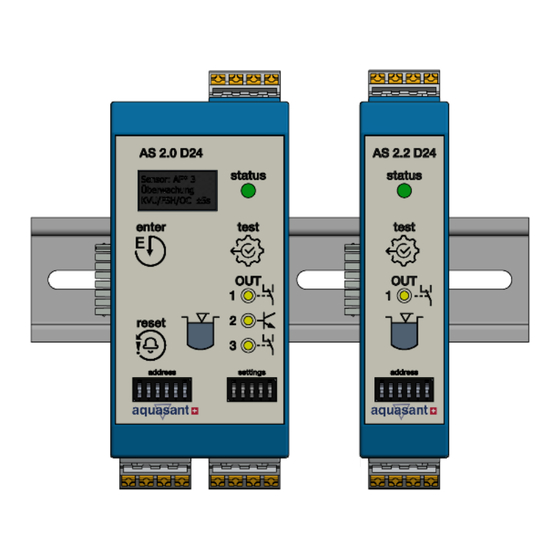
Safety Liquid Switch type AS2.0 D24, 1-channel limit switch
for connection to electro-optical liquid sensors, conductivity
detectors and Namur sensors.
Device designation:
AS2.0 D24
ATEX licence:
(Group, category, ignition protection type, temp. class)
EU type
examination certificate:
SEV 21 ATEX 0523
ATEX:
RL 2014/35/EU / EN IEC 60079-0
RoHS:
RL 2011/65/EU / EN 63000:2018
KVU certificate no.:
321.003 / 302.004
Aquasant Messtechnik AG | CH-4416 Bubendorf
www.aquasant.com
Additional technical documents
The applicable laws, standards and guidelines must be observed
for proper use at the intended place of use. Supplementary
documents include operating instructions, Ex, EMC, SVTI
certificates and technical data.
Target group, application
The responsibility for planning, installation, commissioning,
operation, maintenance and dismantling falls on the plant
operator.
Proper
installation,
maintenance and disassembly of the device may only be carried
out by appropriately qualified personnel. The operating
instructions must be read and understood ahead of time.
Use
Approved for proper and permissible use according to
manufacturer's instructions. The warranty claims and the
manufacturer's responsibility are void in cases of improper
handling. The device is implemented in instrumentation and
control technology as a limit value monitor, e.g. in storage tanks.
The following sensors/probes can be operated with the control
unit:
Electro-optical sensors (2- or 3-conductor technology)
Namur sensors
Conductivity detectors
The operating and environmental conditions must be observed.
The sensor/sensor circuit is intrinsically safe.
Impermissible use
If used improperly, protection of personnel and equipment
cannot be guaranteed.
Assembly/Installation
Do not assemble damaged or dirty equipment. The condition
must be flawless and assembled outside of the hazardous area
in a weather- and shockproof control cabinet. When operating
outdoors, avoid direct sunlight. Do not assemble the control unit
near a heat source. Heat accumulation must be avoided with
good ventilation. The AS2.x control unit is designed with
protection class IP20 according to IEC/EN 60529. The assembly
is designed for a 35mm cap rail according to EN 60715. Only use
the device when stationary. For problem-free operation,
installation
must
be
ensured
2813
II (1) G [Ex ia Ga] IIC
commissioning,
operation,
in
an
environment
contamination degree 2 (or better) according to IEC/EN 60664-
1. All circuits connected to the device must comply with
overvoltage category II (or better) according to IEC/EN 60664-1.
Observe the installation instructions according to IEC/EN 60079-
14. The installation and operation in hazardous areas is only
permitted if in compliance with the requirements according to
IEC/EN 60079-0.
Requirements; cables and connection lines
The following points must be observed when installing cables and
connecting lines:
Permissible wire cross-section of the conductor for the
terminals.
The insulation of the conductors must reach to the terminal.
Wire end splices are not required for corded wires.
The installation must be carried out de-energised
Settings and parameterisation
The standard device configuration and further setting options can
be found in the operating instructions.
Commissioning the device
Before commissioning, the sensor/sensor type must be set to the
desired application using the rotary switch. Additionally, ensure
that the wiring is correct according to the operating
instructions.
Operation, maintenance, repairs
During operation, the device status is shown on the display,
further details are explained in the operating instructions*. A
defective device may only be repaired by Aquasant Messtechnik
AG. The disassembly must be carried out de-energised. The
precise disassembly from the 35mm cap rail is described in the
operating instructions*.
Maintenance, cleaning
The system must be inspected and checked for functionality in
accordance with the regulations of KVU, TTV, SEV etc. by
Aquasant Messtechnik AG or a licensed tank inspection
company. The device cleaning must be carried out de-energised
(if necessary, pull out the mains plug). Under no circumstances is
it permitted to penetrate the device with any object or to open
the housing. The housing can be cleaned with light compressed
air < 2 bar or with a damp cloth (do not use solvents).
Delivery, transport, disposal
Check the packaging and contents for damage. Check the scope
of delivery for completeness and correctness. Use the original
packaging for storage (dry and clean) or transport. Observe
national laws and regulations for the disposal of defective
devices, packaging and any batteries included.
with
Advertisement

Related Manuals for aquasant AS2.0 D24

Summary of Contents for aquasant AS2.0 D24
- Page 1 2 (or better) according to IEC/EN 60664- Identification 1. All circuits connected to the device must comply with Safety Liquid Switch type AS2.0 D24, 1-channel limit switch overvoltage category II (or better) according to IEC/EN 60664-1. for connection to electro-optical liquid sensors, conductivity Observe the installation instructions according to IEC/EN 60079- detectors and Namur sensors.
- Page 2 HL alarm OC delayed output Power supply 24VDC, A1+ / A2- Relay fault message output RS485 Aquasant Messtechnik AG | Postbox 107 | Hauptstrasse 22 | 4416 Bubendorf | Switzerland T: +41 61 935 50 00 | info@aquasant-mt.com | www.aquasant.com...
- Page 3 Operating manual ATEX documentation © 2021 Aquasant Messtechnik AG claims copyright protection for this document. The document may not be modified or supplemented without prior written consent. We reserve the right to make changes to technical details compared to the description, information and illustrations in these operating instructions.
Need help?
Do you have a question about the AS2.0 D24 and is the answer not in the manual?
Questions and answers