Advertisement
Quick Links
Installation Guide
1 General Information
1.1 Wireless remote operating console «PUV-RK» (hereinafter,
PUV-RK) is designed to provide display, entry and exchange
the
information
via
two-way
433.05 ... 434.79 MHz frequency range according to the
«Rielta-Contact-R» exchange protocol.
PUV-RK is intended for operation as a component of a system
that is operated by a control panel (hereinafter, the CP), supporting
wireless «Rielta-Contact-R» exchange protocol.
1.2 Transmitter emitted power does not exceed 10 mW.
1.3 To provide radio exchange between PUV-RK and extension
module two operating frequencies: main and reserve are used. PUV-
RK switches to reserve operating frequency automatically in case of
radio-frequency interference on the main one.
1.4 PUV-RK is powered by lithium power supply battery CR123A
type.
1.5 PUV-RK generates and transfers the following messages:
- «Main Battery Discharge» message if power supply battery
voltage drops lower than 2.4
- «Reserve Battery Discharge» message if power supply battery
voltage drops lower than 2.3
1.6 PUV-RK generates «Tamper» message in case of PUV-RK
removing from the installation place.
1.7 PUV-RK ensures control codes transmission by
pushing and release. Entered codes cleaning is ensured by pressing
the
button.
1.8 PUV-RK provides transmission of an emergency call (panic
button function) by pressing the buttons
seconds.
1.9 PUV-RK is resistant to electromagnetic interferences.
1.10 PUV-RK is designed for continuous operation around the
clock.
2 Specifications
Table 1
Parameter
Operating temperature
Permissible relative humidity +25 °С
Ambient class
IP rating
Dimensions, not more than
Weight, not more than
Operating period under normal climate conditions,
not less than
Average service life, not less than
* background temperature 15 – 35
air-pressure 86 – 106 kPa.
3 Scope of delivery
Each Console unit package contains items listed in Table 2.
Table 2
Name
Wireless remote operating console «PUV-RK»
Lithium battery CR123А
Screw 3-3х30.016
Wall Plug NAT 5x25 SORMAT
Wireless remote operating console «PUV-RK». Installation Guide
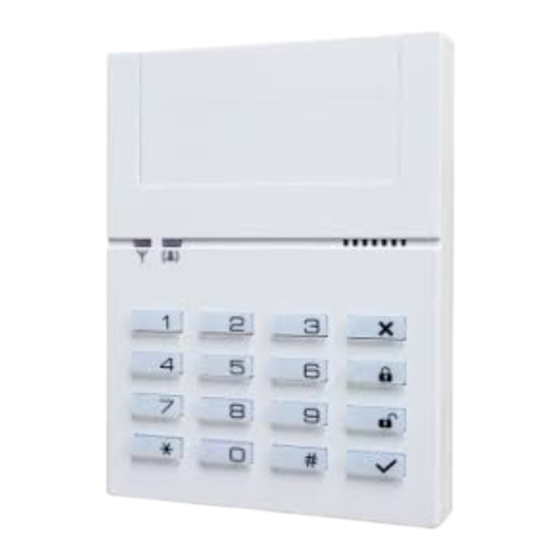
4 Design
comprises the following components (see Figure 1): case
PUV-RK
(7) with the installed printed circuit board (PCB) (8). Power supply
battery should be installed to the holder (9).
PCB comprises: pieso transmitter (10), jumper for sound switching
off (13), «Reset» contacts (12) for
mode, wall tamper (11).
LED indicators of general application (1), (2) located on the front
panel can be switched ON / OFF by the relevant command from CP.
In order to provide control codes entry
buttons, 14 of which generate codes. Keys (3),(4),(5),(6) are used in
combination with numeric keys:
- key
(5) - sending the code combination;
- key
(6) - reset the code combination.
WIRELESS REMOTE
OPERATING CONSOLE
«PUV-RK»
communication
channel
V;
-0.1
V.
-0.1
and # for at least 3
Value
minus 20 ... +50 °С
up to 98 %
Boreal climate*
IP30
120 x 90 x 23 mm
0.12 kg
24 months
8 years
о
С, relative humidity 25 – 75 %,
changing to «Binding»
PUV-RK
is equipped by 16
PUV-RK
6
within
5 LED Indication
PUV-RK comprises the following types of built-in LED indicators
(1), (2):
- «Binding» mode (logging to the control panel (hereinafter, the CP);
- «Communication quality appraisal»;
- «Communication loss»;
- «Battery discharge»;
LED indication modes depend on the PUV-RK state and are listed
in Table 3.
Table 3
State
Operation in
«Binding» mode
«Binding» mode
finishing
button
«Communication
loss» LED
indication
LED indication
«Battery
discharge»
LED indication
«Battery
normal»
Communication
quality
appraising
Sound indication is switched on/off by installing/removing a jumper
on the back side of the PUV-RK (Fig. 1, (13)).
6 Binding with the CP
«Binding» mode is provided for the PUV-RK logging in the CP and
for service information exchange.
Install power supply battery to the holder. Prepare the CP for the
Detector logging in accordance to the CP Installation Guide. Service
LED indicator (Fig. 1, (1)) periodical blinking green means that the
PUV-RK is being in process of binding. In case of service LED indication
absence, close the «Reset» contacts (12) at PUV-RK backside for a
moment. The time during which the PUV-RK operates in the «Binding»
mode is limited to 100 sec. After it expires, the PUV-RK state changes
to the sleep mode. To restore the «Binding» mode, the «Reset» (12)
contacts must be closed for a moment.
7 Operation Aspects
PUV-RK stores in it's buffer not more than 24 pressed buttons.
PUV-RK transmits information about pressed buttons after pressing
QNT.
and release
1 pc.
To ensure energy conservation PUV-RK transfers to energy saving
1 pc.
(sleeping) mode 5 s after the last key press. When entering the energy
3 pcs.
saving mode, the other keys are deactivated and the buffer is cleared.
3 pcs.
PUV-RK provides the mode of periodical radio sessions in order to
1 copy
control it's presence in radio network.
A list of messages and commands supported by the device:
1) to report a set period of going in radio network;
2) to set the established period of radio sessions;
3) to set the frequency lit;
4) to synchronize the session key;
5) to report the status of the terminating device;
6) to report the set frequency lit;
7) to set light and sound indication in command with the CP;
8) to set the start of radiosessions after the set time.
10
1
9
2
3
8
4
5
7
Figure 1
LED Indication
Service LED indicator blinking
green periodically
Service LED indicator lighting
red for 1 sec
Four-shot LED indicator blinking
red
One-shot LED indicator blinking
red during any button pressing
One-shot LED indicator blinking
green during any button
pressing
See Cl. «Communication Quality Appraising»
(6).
11
12
RESET
13
SOUND
Notes
Request for logging in
the CP
When transmitting
data in the absence of
communication
Advertisement

Summary of Contents for Rielta PUV-RK
- Page 1 LED indicator (Fig. 1, (1)) periodical blinking green means that the Operating period under normal climate conditions, 24 months PUV-RK is being in process of binding. In case of service LED indication not less than absence, close the «Reset» contacts (12) at PUV-RK backside for a...
- Page 2 8 Communication Quality Appraising 9 Storage and Transportation Before installing the PUV-RK to it’s place of operation, it is advisable 9.1 The Consoles in their original packing may be shipped by any to appraise the CP communication quality as follows: press...
Need help?
Do you have a question about the PUV-RK and is the answer not in the manual?
Questions and answers