Advertisement
Quick Links
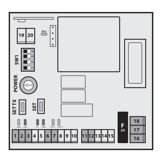
UNIVERSAL CONTROL BOARD FOR 220V SLIDING GATE AUTOMATION
1 2 3
4 5
NO
NC
NC
NC
Safeties
Commands
The MC 200 board is an electronic control unit for the control of
sliding gates with or without friction from the construction
particularly robust and reliable. Prepared for the use of a
clock (timer) to be connected to the START input (with condominium
mandatory) for scheduled openings and closings. Immune come on
induced disturbances and protected against atmospheric discharges
and
electrostatic. The control unit has passed all tests relating to
electromagnetic emissions and immunity to disturbances foreseen
by
current European legislation. In particular, it responds to directives
EMC 89/336/EEC, 92/31/EEC, BT 73/23/EEC and 93/68/EEC.
MC200
DL2
19 20
LSW_C
LSW_O
START
STOP
PH
EDGE
1 2
3
4
5 6 7
8
6 7
8
9
10
NC
NC
Limitswitches
24V power
supply output
WARNING: the installation of this equipment must be. carried out
exclusively by specialized technicians who comply. the safety
regulations in force, as well as the instructions in. this manual. It is in
any case the task of the installer to verify the. type of system and
possibly insert upstream. of the equipment those safety devices
(switches. differential and magnetothermic) necessary to meet
current. regulations. The manufacturer disclaims all liability for
damage to. persons or property resulting from improper installation,
improper use and. unreasonable, tampering and non-compliance
with. current legislation by the installer or user.
9
10 11 12
13
14
15
11 12
13
Courtesy light 220V
Flashing light 220V
18
F
17
5A
16
14
15
17
18
16
M
L
N
220V Power
Motor
supply input
Protect the equipment with a 6A circuit breaker
or with a 16A single-phase switch complete with fuses.
It is necessary to respect phase and neutral polarities in the line
230vac supply (terminal 18 = phase, terminal 16 = neutral,
terminal 17 ground). For power circuits (lamp and motor outputs)
the minimum cross-section shall be 1,5 mm2 . For power, auxiliary
and control (inputs) it is necessary to always use connecting cables
separated to avoid interference or failure caused by induced
voltages (do not use a single multipole cable).
In the case of lines longer than 50 m it is advisable
disconnect the control circuits with relays at the control panel
command.
The inputs n.c.(photocell, coast and stop) if they were not
used, must be connected to the common (terminal 3 or 6)
by means of bridges.
19 20
Antenna
Advertisement

Related Manuals for InDeM automation MC200


Summary of Contents for InDeM automation MC200
- Page 1 MC200 UNIVERSAL CONTROL BOARD FOR 220V SLIDING GATE AUTOMATION 19 20 LSW_C LSW_O START STOP EDGE 5 6 7 10 11 12 1 2 3 11 12 19 20 Courtesy light 220V Limitswitches Safeties 24V power Commands Antenna 220V Power...
- Page 2 CONNECTIONS 1 - 3 Start button (N.O.) stepping function, press again to stop the 11 - 12 Flashing light output motors 230 Vac max 100 W. START FLASH (if auto-closing is set, invert them while closing). 2 - 3 12- 14 Courtesy light output (90 sec.).
- Page 3 - AUTOMATIC PROGRAMMING 1) Press SET button for 10s until the motor starts (Led DL2 flashes): 584718 first, the motor moves towards the closing limitiswitch, then does a complete cycle, slowing down automatically 5s before reaching the limitswitches. - MANUAL PROGRAMMING 1) Press and release SET button to enter in program mode.
- Page 4 MC200 PROBLEM SOLVING PROBLEM SOLUTION DL2 Led flashes quickly when power on NC Contact open (safeties wiring error) the board Check inputs status (safeties leds lit) With slow down movement on, the gate 1) Increase Power trimmer doesn’t get to the limitiswitch.
Need help?
Do you have a question about the MC200 and is the answer not in the manual?
Questions and answers