Table of Contents
Advertisement
Quick Links
Installation Manual
U S E R M A N U A L
ICA Turn-Assist AI40
Turn-Assist
Blind Spot Information System
AXION camera systems comply with current CE and EMC regulations. Copyright © 2020
AXION AG
All rights reserved. No part of this publication may be reproduced, processed or transmitted
in any form or by any means, including photocopying, recording or any other electronic or
mechanical process, without the written permission of the publisher.
The AXION camera monitor systems comply with the current CE and EMC regulations.
Copyright © 2020 AXION AG
All rights reserved. No part of this publication may be reproduced in any form, including
photocopying, recording, or any other electronic or mechanical process without the written permission of the publisher.
03/2022 EN
Version: 1.00
Changes and errors excepted.
Advertisement
Table of Contents

Related Manuals for Axion ICA Turn-Assist AI40

Summary of Contents for Axion ICA Turn-Assist AI40
- Page 1 ICA Turn-Assist AI40 Turn-Assist Blind Spot Information System AXION camera systems comply with current CE and EMC regulations. Copyright © 2020 AXION AG All rights reserved. No part of this publication may be reproduced, processed or transmitted in any form or by any means, including photocopying, recording or any other electronic or mechanical process, without the written permission of the publisher.
-
Page 2: Table Of Contents
Table of contents General _________________________________________________________________3 General notes_____________________________________________________________3 Explanation of the safety instructions __________________________________________3 Storage instructions ________________________________________________________3 Intended use _____________________________________________________________4 Disclaimer________________________________________________________________5 Warranty ________________________________________________________________5 Product information _______________________________________________________6 Scope of delivery __________________________________________________________6 Technical data ____________________________________________________________7 Operating and display elements ______________________________________________8 Range of use______________________________________________________________8 Functional description ______________________________________________________9 Assembly and commissioning________________________________________________10 Safety instructions for assembly ______________________________________________10... -
Page 3: General
This document describes the function, instructed drivers who have the qualification and installation, operation, maintenance and suitability to drive the motor vehicle. troubleshooting of the ICA Turn-Assist AI40 Make sure you have read and understood the turn system. complete instructions and all safety... -
Page 4: Intended Use
Intended use The ICA Turn-Assist AI40 is designed exclusively for use in closed vehicles with 12V/24V power supply. Qualification and suitability for driving the vehicle cannot be compensated or replaced by using the turn assistance system! The road traffic regulations must always be followed in full. The system does not... -
Page 5: Disclaimer
Neither AXION AG nor any manual. AXION AG also reserves the right to of its affiliates or subsidiaries shall be held revise this publication at any time without responsible or liable for any misuse of the notice to any party. -
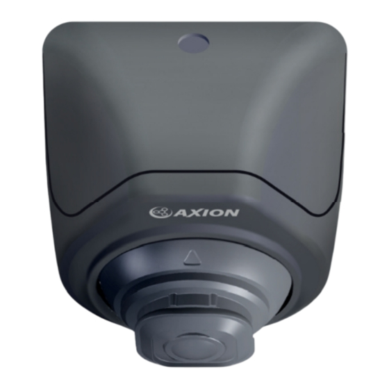
Page 6: Product Information
Product information Scope of delivery Figure Description Item number AI camera DBC-AI40 Control unit (MCU) ICA-MCU40 LED warning light ICA-WLED40 Warning buzzer (Buzzer) ICA-WBZ40 Connection cable set ICA-MCC40 Y-connection cable ICA-MCY40 Extension cable 10m WPC-4010 ICA-GPSM40 GPS module Screws + nuts Mounting material... -
Page 7: Technical Data
Technical Data Camera Specifications - DBC-AI40: Dimensions 50 mm x 46 mm (WxD) Operating voltage 9-36 Vdc Current consumption ~200mA @ DC 12V Sensor format CMOS Resolution 1280x960 (720p) HDR dynamic range >100dB Minimum brightness 0.1 lux Video format CVBS / AHD Viewpoint H: 165°... -
Page 8: Operating And Display Elements
Operating and Display elements The system can be operated via the button included in the scope of delivery. A distinction is made between two operating options: Short press (<1s): Quick adjustment of buzzer volume, move to next menu item. Long press (>3s): Opens the settings menu / selection or confirmation of a menu item, a short tone is played as feedback. -
Page 9: Functional Description
Functional description The ICA Turn-Assist AI40 turn assistance system is a camera-based system. It consists of a side camera with integrated AI algorithm for observing the coverage area, a control unit for signal processing and the warning device consisting of LED and buzzer. -
Page 10: Assembly And Commissioning
Assembly and commissioning Safety instructions for assembly Observe the safety instructions and requirements specified by the vehicle manufacturer and the automotive trade! Make sure you have read and understood the instructions and all safety information before using this product. Failure to follow these instructions can result in serious injury or death. -
Page 11: Mounting Material
• Never use the device outside the specified tempera- ture range • Do not use the device if the relative humidity is above the specified limit. • Do not use the device if it interferes with safe driving of the vehicle. •... -
Page 12: Wiring Diagram
Wiring Monitor diagram (optional and for commissioning) AI camera LED warning people Warning buzzer (optional and for commissioning) Control unit Control knob (button)* Yellow ACC (ignition plus 12/24 Vdc) Black GND (ground Brown Kl.31) Right Indicator (turn Orange signal right) Left Indicator White (turn signal left) Speed (speed signal analog) -
Page 13: Assembly Instructions
Assembly instruction The camera must be mounted in the attachment area provided. Measurements are taken from the floor to the camera lens. Distance to the front edge: from 1.0 m to 4.0 m Possible mounting height: from 2.3m to 3.8m The recommended mounting height is within the green marked area, if necessary the camera can be mounted within the yellow marked area. - Page 14 Housing variants Standard housing ICA-CB401 Design Case ICA-CB402 Design housing ICA-CB202B Spacer ICA-CB203C suitable for ICA-CB402, ICA-CB202B Camera mounting 1. (If bracket is necessary) Firmly attach camera mounting bracket to the body of the vehicle 2. Connect camera cable with extension cable WPC-4010 3.
-
Page 15: Alignment Of The Camera
The long, horizontally dashed line is used to align the camera along the outer edge of the vehicle. AXION recommends the ICA calibration mat MM1100 as a simple and quick solution: place the calibration mat along the outer... -
Page 16: Operation And Settings
Operation and Settings An external button is required for operation (ICA-EBT40). This is not part of the scope of delivery and can be purchased as mounting material. A distinction is made between two operating options: Short press (<1s): Long press (>3s): •... - Page 17 Menu item Description Possible settings Indicates the coverage area. Distinction 1: LP (Standard) Detection Area between low (LP) and high (HP) 2: HP mounting position. For setting vehicle detection as lane 1: N/A (default) change assist. N/A means vehicle detection 2: 40 km/h is OFF.
-
Page 18: Calibration Of The Speed
Calibration of the speed The turn assistance system requires a speed signal for full functionality. The speed signal from the vehicle is used as the source. Alternatively, the enclosed GPS receiver can be used permanently for operation. When using the GPS receiver, no calibration is necessary. Note: Ensure good reception when using the GPS module. -
Page 19: Troubleshooting
Troubleshooting Error pattern Possible causes Solutio • Faulty connection • Check connections according to connection diagram System does not • Check voltage supply start • Check plug connection and • Plug connection or Warning LED does lines cable damaged not light up at •... -
Page 20: Repairs
The recycling of materials contributes to the conservation of natural resources. Simplified EU Declaration of Conformity AXION AG hereby declares that the ICA Turn Assist AI40 is in compliance with EU Directive 2014/30EU. The full text of the EU Declaration of Conformity under the following mail: service@axionag.de...
Need help?
Do you have a question about the ICA Turn-Assist AI40 and is the answer not in the manual?
Questions and answers