Advertisement
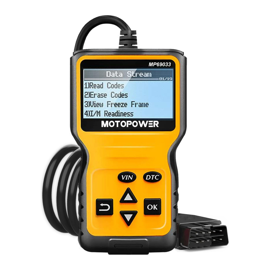
- 1 About the Code Reader
- 2 On-Board Diagnostics [OBD] II
- 3 Diagnostic Trouble Codes [DTCs]
- 4 Location of the Data Link Connector [DLC]
- 5 Using the Code Reader
- 6 Freeze Frame Data
- 7 I/M Readiness
- 8 View Vehicle Information
- 9 View Live Data
- 10 Set Up
- 11 FAQ
- 12 Specification
- 13 Safety Precautions
- 14 Documents / Resources
About the Code Reader

- CABLE - Connects the Code Reader to the vehicle's Data Link Connector (DLC).
- LCD Display - Displays test results, Code Reader functions and Monitor status information.
- VIN - Vehicle Identification Number
- Up roll
- Return button
- DTC - One-button Diagnostic Trouble Code (DTC) check. Each fault is assigned a code number that is specific to that fault.
- Confirm - Confirm the selection in the menu.
- Down roll
On-Board Diagnostics [OBD] II
What is OBD?

On-Board Diagnostics (OBD) is an automotive electronic system, which is capable of a self-diagnosis, indicating and reporting the possible problem within the vehicle. It gives you or the technician the opportunity to easily access the information about the 'health' of your car and solve the problem.
The OBD II system is designed to monitor emission control systems and key engine components by performing either continuous or periodic tests of specific components and vehicle conditions. When a problem is detected, the OBD II system turns on a warning lamp (MIL) on the vehicle instrument panel to alert the driver typically by the phrase" Check Engine" or "Service Engine Soon". The system will also store important information about the detected malfunction so that a technician can accurately find and fix the problem. Here below follow three pieces of such valuable information:
- Whether the Malfunction Indicator Light (MIL) is comm anded on or off.
- Which, if any, Diagnostic Trouble Codes (DTCs) are stored.
- Readiness Monitor Status.
How Does it Work?
There are multiple sensors in your vehicle and each sensor sends signal to your vehicle's computer - the Electronic Control Unit (ECU). The ECU uses the signal/information and adjusts different elements in order.
Diagnostic Trouble Codes [DTCs]
Diagnostic Trouble Codes (DTC Look Up)
OBDII Diagnostic Trouble Codes are codes that are stored by the onboard computer diagnostic system in response to a problem found in the vehicle. These codes identify a particular problem area and are intended to provide you with a guide as to where a fault might be occurring within a vehicle. OBDII Diagnostic Trouble Codes consist of a five-digit alphanumeric code. The first character, a letter, identifies which control system sets the code. The other four characters, all numbers, provide additional information on where the DTC originated and the operating conditions that caused it to be set.
Below is an example to illustrate the structure of the digits:
DIAGNOSTIC TROUBLE CODES EXAMPLE

Location of the Data Link Connector [DLC]
![Location of the Data Link Connector [DLC]](http://static-data2.manualslib.com/pdf7/362/36149/3614864-motopower/images/motopower-mp69033-location-of-the-data-link-connector-dlc-47753.jpg "MOTOPOWER - MP69033 - Location of the Data Link Connector [DLC]")
The DLC (Data Link Connector or Diagnostic Link Connector) is the standardized 16-cavity connector where diagnostic scan tools interface with the vehicle's on-board computer. The DLC is usually located 12 inches from the center of the instrument panel (dash), under or around the driver's side for most vehicles. If the Data Link Connector is not located under the dashboard, a label should be there revealing its location. For some Asian and European vehicles, the DLC is located behind the ashtray and the ashtray must be removed to access the connector. If the DLC cannot be found, refer to the vehicle's service manual for the location.
Using the Code Reader
Connection
CODE RETRIEVAL PROCEDURE
Never replace a part based only on the DTC definition. Each DTC has a set of testing procedures, instructions and flow charts that must be followed to confirm the location of the problem. This information is found in the vehicle's service manual. Always refer to the vehicle's service manual for detailed testing instructions.

Check your vehicle thoroughly before performing any test
ALWAYS observe safety precautions whenever working on a vehicle. See Safety Precautions for more information.
- Turn the ignition off.

- Locate the vehicle's 16-pin Data Link Connector (DLC).
- Connect the Code Reader's cable connector to the vehicle's DLC. The cable connector is keyed and will only fit one way.

- If you have problems connecting the cable connector to the DLC, rotate the connector 180o and try again. If you still have problems, check the DLC on the vehicle and on the Code Reader. Refer to your vehicle's service manual to properly check the vehicle's DLC.

- After the Code Reader's test connector is properly connected to the vehicle's DLC, the screen will tum on to confirm a good power connection.

- Tum the ignition on. DO NOT start the engine.

- The Code Reader will automatically link to the vehicle's computer.

Read Codes
- If the LCD display is blank, it indicates there is no power at the vehicles's DLC Check your fuse panel and replace any burned-out fuses. If replacing the fuse(s) does not correct the problem, see your vehicle's repair manual to locate the proper computer (PCM) fuse/circuit. Perform any necessary repairs before continuing.
- After 4-5 seconds, the Code Reader will retrieve and display any Diagnostic Trouble Codes that are in the vehicle's computer memory.
- If the connection fails, it means that the Code Reader is unable to communicate with the vehicle's computer.
Do the following:
- Tum the ignition key off, wait for 5 seconds and tum the key back on to reset the computer.
- Make sure your vehicle is OBD2 compliant.
- Read and interpret the Diagnostic Trouble Codes using the LCD display.


The Code Reader will display a code only if codes are present in the vehicle's computer memory. If no codes are present, a "0" will be displayed


If more than one code is present, select a specific code to display the detected problem.

Visit the manufacturer's website for Fault Code Definitions. Match the retrieved DTC(s) with those listed. Read the associated definition(s), and see the vehicle's service manual for further evaluation.
Erase Codes
ERASING DIAGNOSTIC TROUBLE CODES (DTCs)
When the Code Reader's ERASE function is used to erase the DTCs from the vehicle's on-board computer, "Freeze Frame" data and manufacturer-specific enhanced data are also erased
If you plan to take the vehicle to a Service Center for repair, DO NOT erase the codes from the vehicle's computer. If the codes are erased, valuable information that might help the technician troubleshoot the problem will also be erased.

Erasing DTCs does not fix the problem(s) that caused the code(s) to be set. If proper repairs to correct the problem that caused the code(s) to be set are not made, the code(s) will appear again (and the check engine light will illuminate) as soon as the vehicle is driven long enough for its Monitors to complete their testing.
Freeze Frame Data
What is Freeze Frame Data?
In simple words, whenever the computer detects a fault and illuminates the CEL, it also clicks and stores freeze frame data related to the issue. This data is essentially a snapshot from a number of components and sensors. You can view this information to find the cause of the problem. It is also a legal requirement in some cases to capture and store emission-related information. This captured data is known as freeze frame data.


Viewing OBD2 Freeze Frame Data
Viewing OBD2 freeze frame data can be complicated for people who do not know much about OBD scan tools. The information will help you identify why the engine light is on so you can come up with a solution. The data will tell you a lot about your vehicle at the time of the error. This includes the condition of the engine whether it was warmed up or cold. It may also give information regarding the fuel. You can use this data to go in the right direction.
How to Read Freeze Frame Data?
Your vehicle talks to you in a language of its own. You will need to understand this language to be able to read freeze frame data.
You can search online for specific codes or try the DTC feature.
How can I Clear Freeze Frame Data using an OBD2 Scan Tool?
The system will automatically remove DTC data once your vehicle completes a specific number of good trips, i.e: trips without faults.
You will also lose freeze frame data if there is no power supply to the PCM. Also, you can manually choose to delete this information by going into the system and delete the data with the scan tool.
I/M Readiness
What is I/M Readiness?
Signals or codes for emission testing which state that all the vehicle's on-board emissions diagnostics have been run.

How do I check my I/M readiness?
To check if the readiness codes are set, tum the ignition switch to the ON (II) position, without starting the engine. The MIL will come on for 20 seconds. If it then goes off, the readiness monitors are set. If it blinks five times, the readiness monitors are not set
What are the monitors?
- Misfire Monitor
- Fuel System Monitor
- Comprehensive Component Monitor EGR - EGR System Monitor
- Oxygen Sens Mon - Oxygen Sensor Monitor
- Catalyst Mon - Catalyst Monitor
- EVAP System Monitor - Evaporation System monitor
- Oxygen Sens htr - Oxygen Sensor heater Monitor
- Sec Air System - Secondary air monitor
- Htd Catalyst - Heating catalyst monitor
- AC Refrig Mon - NC system monitor
What are MIL codes?
The Malfunction Indicator Lamp (MIL) or CHECK ENGINE light as it is more commonly called, is essentially an emis- Sion warning light. If the light comes on, it means the Onboard Diagnostics II system (OBD II) has detected an emissions-related problem.
View Vehicle Information
Vehicle dentification Number (VIN)
VIN stands for Vehicle Identification Number. A unique set of 17 numbers and letters, your VIN holds all kinds of information about your car, including the manufacturer, where and when the car was built and information about the car, including the transmission.


View Live Data
Real-time data view of vehicle operating condition
Live data gives you real-time feedback on some of the functions of your car. These include fuel trim and operating temperature values. This is one of the most useful features of OBD2 scanners.


Set Up
- Language
Use the Up/Down scroll buttons to select the language.


- Unit of measure
Choose the unit of measure - English or Metric


- Contrast
Adjust the screen contrast.


FAQ
- Is the Scanner Powered by built-in battery?
No. It doesn*t include any battery inside. powered by the OBD2 port of the vehicle directly. Just plug into the OBD2 port for opertion. - Why does the screen not turn on when plug-in?
Check your fuses to see if any have gone bad. A blown-out fuse is one of the usual reasons why an OBD2 port isn't communicating. Remember that your car might have more than one fuse box. - If my OBD2 has power but won't connect, what should I do?
Most OBD2 won't connect because it has no power. However, if it has power but wont connect, you may want to check its connection to your entire system. In most cases, it can be a cabling problem, or the OBD2 itself isn't working. If the problem cannot be solved after reconnection, contact the MOTOPOWER customer service for assistance, - Does the obd2 scanner support abs, airbag/SRS, oil codes?
It is able to read and clear check engine information which is part of OBDII system, but it cannot work with non-OBDII systems, including ABS / Airbag / Oil Service Light, etc. - Why the detected error codes cannot be erased?
When you find the fault codes, please fix the problem before erasing the codes, If the codes erased without the problem fixed, the engine fautt light may turn on again in the future. - Check engine light came on, but after hooking this up, it reads no codes. Why it can't find them?
- The scanner is not compatible with the make or model of the car.
- The vehicle is emitting emissions which are higher than the Environmental Protection Agency mandates.
- There were codes erased without the problems were fixed. And the ECM was disabled and prevented from storing codes.
Specification
- Input Voltage: 8-15VoIts DC
- Screen Display: 128 x 64 pixel LCD
- Working Temperature: -20C to 60C
- Storage Temperature: -30 C to 80C
- Compatibility: Supports 9 protocols compatible with most 1996 US-Based, 2000 EU-Based and Asian cars.
- Protocols Supported:
- SAE J1850 PWM (41.6Kbaud)
- SAE J1850 VPW (10.4Kbaud)
- IS09141-2(5 baud init. 10.4Kbaud)
- IS0142304 -4 KWP (5 baud init, 10.4 Kbaud)
- IS014230-4 KWP (fast init, 10.4 Kbaud)
- IS015765-4 CAN (11 bit ID, 500 Kbaud)
- IS015765-4 CAN (29 bit ID, 500 Kbaud)
- IS0157654 CAN (11 bit ID, 250 Kbaud)
- IS015765-4 CAN (29 bit ID, 250 Kbaud)
Safety Precautions
This manual describes common test procedures used by experienced service technicians. Many test procedures require precautions to avoid accidents that can result in personal injury, and/or damage to your vehicle or test equipment. Always read your vehicle's service manual and follow its safety precautions before and during any test or service procedure Always observe the following genera/ safety precautions:

When an engine is running, it produces carbon monoxide, a toxic and poisonous gas. To prevent serious injury or death from carbon monoxide poisoning, operate the vehicle ONLY in a well-ventilated area

To protect your eyes from propelled objects as well as hot or caustic liquids, always wear approved safety eye protection.

When an engine is running, many parts (such as the coolant fan, pulleys, fan belt etc.) turn at high speed. To avoid serious injury, always be aware of moving parts. Keep a safe distance from these parts as well as other potentially moving objects.

Engine parts become very hot when the engine is running. To prevent severe burns, avoid contact with hot engine parts.

Before starting an engine for testing or troubleshooting, make sure the parking brake is engaged. Put the transmission in park (for automatic transmission) or neutral (for manual transmission). Block the drive wheels with suitable blocks.

Connecting or disconnecting test equipment when the ignition is ON can damage test equipment and the vehicle's electronic components. Turn the ignition OFF before connecting the Code Reader from the vehicle's Data Link Connector (DLC).

The vehicle's battery produces highly flammable hydrogen gas. To prevent an explosion, keep all sparks, heated items and open flames away from the battery.
- Service Procedures
If you have any questions, please contact our customer service team directly. Please email to customerservice@motopowers.com for any technical assistance and service.
Documents / ResourcesDownload manual
Here you can download full pdf version of manual, it may contain additional safety instructions, warranty information, FCC rules, etc.
Advertisement
Need help?
Do you have a question about the MP69033 and is the answer not in the manual?
Questions and answers