Advertisement
Notice
Throughout this publication, safety alerts labeled WARNING and CAUTION (accompanied by the symbol  ), are used to alert you to special instructions concerning a particular service or operation that may be hazardous if performed incorrectly or carelessly. Observe these alerts carefully.
These safety alerts alone cannot eliminate the hazards that they signal. Strict compliance to these special instructions when performing the service, plus common sense operation, are major accident prevention measures.

Indicates a hazardous situation which, if not avoided, could result in death or serious injury.

Indicates a hazardous situation which, if not avoided, could result in minor or moderate injury.
Additional alerts provide information that requires special attention:
NOTICE
Indicates a situation which, if not avoided, could result in engine or major component failure.

Identifies information essential to the successful completion of the task.
NOTE: Indicates information that helps in the understanding of a particular step or action.
GENERAL INFORMATION
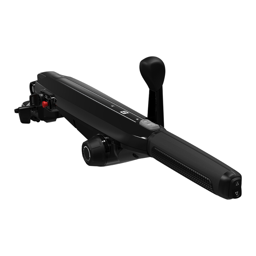
Tiller Handle Components

- Tiller lock release lever
- Heated throttle grip control (if equipped)
- Ignition key switch
- Lanyard stop switch
- Lanyard
- Throttle grip friction knob
- Troll speed control switch (if equipped)

- Power trim switch (if equipped)
- Throttle grip
- Gear shift handle
- Warning light panel
- Spare lanyard clip
- Down stop adjustment knob
- Tiller handle tilt friction adjustment jam nut
Warning Light Panel
A panel on the top of the tiller handle contains five warning icons that light up to notify the operator of an unsafe condition. The translucent panel hides the icons when they are not illuminated.

| Ref | Icon | Cause | Action to take |
| a. | Warning | Engine fault | Contact an authorized dealer for service. |
| b. | Battery | The battery voltage is too low. | Turn off unnecessary accessories to allow the battery to recharge. If the light persists, have the battery and charging system checked by an authorized dealer. |
| c. | Lanyard clip | The lanyard clip has been removed from the lanyard stop switch. | Attach the clip in order to start the engine. |
| d. | Oil pressure | The oil pressure is below the safe level. | Stop the engine immediately, unless doing so puts the boat occupants in danger. Check the oil level, and add oil to bring it up to the specified level. Upon returning to port, check the engine for signs of an oil leak. Contact an authorized dealer for service. |
| e. | Engine overheat | The engine coolant temperature is above the safe level. | The engine will operate with reduced power (Guardian mode), to allow a return to port. Check the cooling system for blockages. Contact an authorized dealer for service. |
General Tiller Handle Precautions
Never stand on the tiller handle or use it as a step.
Ensure that the tiller handle will not contact anything that can damage it throughout the outboard engine's entire tilt range.
Mercury Marine has tilt limit kits available. These kits limit the upward tilting range of the outboard to prevent interference. Contact an authorized Mercury Marine dealer for parts and installation.
Lanyard Stop Switch
This tiller handle is equipped with a lanyard stop switch. One end of the lanyard cord has a clip that is meant to be inserted around the stop switch on the tiller handle. It holds the switch closed, allowing the engine to operate. The other end of the lanyard cord has a clip to attach to the operator's personal flotation device (PFD) or wrist. The lanyard cord is coiled to make its at‑rest condition as short as possible, to minimize the likelihood of lanyard entanglement with nearby objects.

- Lanyard cord clip
- Lanyard stop switch (on the tiller handle)
ADJUSTMENTS
Throttle Grip Friction Adjustment
Avoid serious injury or death from unattended boat operation. Even with throttle grip friction and steering friction applied, the operator must remain at the controls and be ready to evade hazards.
Turn the throttle grip friction knob to set and maintain the throttle at the desired speed. The throttle grip friction knob can be adjusted to increase or decrease the amount of effort needed to rotate the throttle grip.
- Turn the throttle grip friction knob clockwise to increase friction.
- Turn the throttle grip friction knob counterclockwise to decrease friction.

- Throttle grip friction knob
- Throttle grip
Throttle Grip Rotation Configuration
NOTE: This procedure changes the throttle grip rotation from the factory default of counterclockwise rotation to clockwise rotation. To change from clockwise to counterclockwise rotation, move the pin from the fore pinion gear to the aft pinion gear.
- Remove and retain the nine screws that secure the top cover to the tiller handle.

- Remove the cotter pin from the pin in the aft pinion gear.
- Ensure that the throttle grip is at idle, and remove the pin from the aft pinion gear.
- With the throttle grip set to idle, position the fore pinion gear so that the hole in the gear aligns with the hole in the throttle shaft.
- Install the pin in the fore pinion gear.
- Secure the pin with the cotter pin.

- Throttle shaft
- Hole in gear aligned with hole in throttle shaft
- Fore pinion gear ‑ secure for clockwise rotation
- Aft pinion gear ‑ secure for counterclockwise rotation
- Pin
- Cotter pin
- Install the top cover and secure it with nine screws.
- Twist the throttle grip to confirm desired operation.


Tiller Handle Tilt Friction Adjustment
The tiller handle pivot screw can be adjusted to increase or decrease the amount of effort needed to move the tiller handle up and down. Loosen the jam nut on the end of the pivot screw and tighten or loosen the pivot screw to obtain the desired friction setting on the tiller handle. Hold the pivot screw from turning and tighten the jam nut to the specified torque.

- Jam nut
| Description | Nm | lb‑in. | lb‑ft |
| Jam nut | 47.5 | – | 35 |
Tiller Handle Operating Position Adjustment
The down stop adjustment knob sets the angle of the tiller handle operating position. Use this knob to raise or lower the tiller handle operating position.

Tiller Handle Yaw
The tiller handle yaw allows the operator to change the horizontal angle of the handle up to 18° left or right of center. Each marked increment is 6°.
- Remove the rubber boot covering the clamp nut.
- Use a 15 mm socket to loosen the clamp nut so it is almost completely off.

- Rubber boot
- Clamp nut
- Loosen the 6 mm Allen socket head screw.

- 6 mm Allen socket head screw
- Lift the clamp and rotate the tiller handle to the desired angle.
- Tighten the clamp nut to the specified torque and install the rubber boot.

- Clamp
- Clamp nut
Description Nm lb‑in. lb‑ft Clamp nut 50 – 36.9
- Tighten the 6 mm Allen socket head screw to the specified torque.
Description Nm lb‑in. lb‑ft 6 mm Allen socket head screw 24.4 – 18


Steering Friction Adjustment
Insufficient friction adjustment can cause serious injury or death due to loss of boat control. When setting the friction adjustment, maintain sufficient steering friction to prevent the outboard from steering into a full turn if the tiller handle is released.
Avoid serious injury or death from unattended boat operation. Even with throttle grip friction and steering friction applied, the operator must remain at the controls and be ready to evade hazards.
35–60 HP MODELS
35–60 hp models include a copilot lever to set the steering friction. Adjust the copilot lever to achieve the desired steering friction (drag) on the tiller handle. Move the lever to starboard to increase the friction, or move the lever to port to decrease the friction. A quick reference decal is located on the transom clamp.

- Tiller handle
- Copilot lever (friction adjustment)
- Decal
65–115 HP MODELS
65–115 hp models use a copilot rod to set the steering friction. Adjust the copilot knob to achieve the desired friction (drag) on the tiller handle. Turn the knob clockwise to increase the friction or turn the knob counterclockwise to decrease the friction.

Starboard view
- Tiller handle
- Copilot knob
- Copilot rod
FEATURES AND CONTROLS
Tiller Handle Tilt Lock
The tiller handle can be tilted for convenient handling during transportation and storage, or for inclined tiller operation. Push the lock release lever down to allow the tiller handle to be raised or lowered.

- Lock release lever in locked position
- Lock release lever in unlocked position
With the lock release lever in the locked position, the tiller handle will ratchet through three inclined operating positions. When trailering, always lock the tiller arm in the trailering (fully raised) position.

- Normal operating position (no incline)
- Inclined operating positions
- Trailering (fully raised) position
- Lock release lever
Gear Shifting
Observe the following:
- Never shift the outboard into gear unless the engine is at idle.
- Do not shift the outboard into reverse when the engine is not running.
- Three gear shift positions provide operation: forward (F), neutral (N), and reverse (R).
- Reduce engine speed to idle before shifting.
- Always shift the outboard into gear with a quick motion.
- After shifting the outboard into gear, the throttle grip can be rotated to increase speed.

- Forward (F)
- Neutral (N)
- Reverse (R)
Troll Control
Abandoning the helm while using troll control may result in serious injury or death. Troll control manages engine RPM only. Do not abandon the helm with troll control engaged.
Troll control allows the operator to maintain a set trolling speed without using the throttle. Refer to the following table for the trolling speed range.
| Trolling Speed Range | |
| 35–60 hp FourStroke | 700–1000 RPM |
| 75–115 hp FourStroke | 550–1000 RPM |
The troll control can be shut off anytime by rotating the throttle grip out of the idle position. On 75‑115 hp models, troll control will also be disabled by moving the shift handle to neutral.
NOTE: Slight rotation of the throttle grip while steering the outboard can disengage the troll control. Adjust the throttle friction to prevent this.
Turn on the troll control as follows:
- With the engine running, shift the engine into gear.
- Set the throttle grip to the idle position.
- Press either the (+) or (–) button to turn on the troll control.
- The light will be illuminated when the troll control is turned on.
- Press the (+) button to increase troll speed and (–) to decrease troll speed.

- Throttle grip idle position
- Decrease troll speed
- Light
- Increase troll speed

Turn off the troll control as follows:
- Rotate the throttle grip out of the idle position, or move the shift handle to neutral (75‑115 hp models only).
- The light will go out when the troll control is turned off.
Power Trim
The power trim switch, if equipped, is located at the end of the throttle grip. It allows the operator to adjust the angle of the outboard with respect to the boat transom. Refer to Power Trim Operation in the appropriate outboard operation manual.

- Power trim switch
- Throttle grip
Ambidextrous Operation
The tiller handle can be configured for either right‑hand or left‑hand operation.
- The shift lever can be positioned on either the port or starboard side of the tiller handle. The factory configuration is with the shift lever on the port side of the tiller handle. Changes to this configuration should be performed only by an authorized Mercury Marine dealer.
- The throttle grip is factory configured to rotate counterclockwise to increase speed from idle to wide‑open throttle. This configuration can be changed to clockwise rotation. Refer to the Throttle Grip Rotation Configuration procedure, or have this procedure performed by an authorized Mercury Marine dealer.
Heated Throttle Grip
Some models include a heated throttle grip for comfortable cold‑weather operation. The control for the heater is at the pivot end of the tiller handle. The heater has three heat settings. Three LEDs illuminate to indicate the current setting. Pressing the button cycles through the settings:
- Low heat, indicated by a single LED
- Medium heat, indicated by two lit LEDs
- High heat, indicated by three lit LEDs
- Heater off, indicated by no lit LEDs

- Tiller handle pivot
- Throttle grip heater button
- High setting LED
- Medium setting LED
- Low setting LED
The heating element may take a few minutes before heat is felt through the grip.
If the battery charge is too low, the heater will automatically shut off to preserve starting power.
OPERATION
Before Starting the Engine
- Read the pre‑starting checklist and pre‑starting instructions in the appropriate outboard operation manual.
- If the engine has less than 100 hours of operation, read the engine break‑in procedure in the appropriate outboard operation manual.
- Check the tiller handle for any loose fasteners or components.
- Ensure that all tiller handle adjustments are set to the operator's preference. Refer to Adjustments.
Starting the Engine
- Open the fuel tank vent screw (in the filler cap) on manual venting type fuel tanks.
![]()
- Models with primer bulb ‑ Position the fuel line primer bulb so the arrow on the side of the bulb is pointing up. Squeeze the fuel line primer bulb until it feels firm.
![]()
- Ensure that the lanyard is engaged with the lanyard stop switch and the lanyard cord is attached to the operator's wrist or personal flotation device (PFD).

- Lanyard cord clip (attach to the operator)
- Lanyard stop switch (on the tiller handle)


If the lanyard is not engaged with the lanyard stop switch, the lanyard clip light will illuminate and the engine will not start.

- Shift the outboard to the neutral position. A detent provides feedback to the operator to ensure the gearcase is in neutral.

- Forward (F)
- Neutral (N)
- Reverse (R)
- Ensure that the throttle grip is in the idle position.

- Idle position


NOTE: For initial start of a new engine, or for an engine that ran out of fuel or was drained of fuel, the fuel system should be filled by following the procedure in the Starting the Outboard section of the outboard operation manual.
- If the engine is flooded, advance the throttle grip to half throttle position.
- Turn the ignition key to the START position.
- Smart Start models ‑ Immediately release the key. The electronic starting system will automatically crank the engine for starting. If the engine fails to start, the engine will stop cranking. Turn the key to the START position again until the engine starts.
- Other models ‑ If the engine fails to start within ten seconds, return the key to the ON position, wait 30 seconds, and try again.
![]()
- After the engine starts, check for a steady stream of water flowing out of the water pump indicator hole.
![]()


If no water flows out of the water pump indicator hole, stop the engine and check the cooling water intake for obstruction. If no obstruction is found at the intake, there may be an internal blockage within the cooling system or the water pump may have failed. Either of these conditions will cause the engine to overheat, resulting in engine damage. Have the outboard checked by an authorized dealer.
WARMING UP THE ENGINE
Before getting underway, allow the engine to warm up at idling speed for three minutes.
Stopping the Engine
Reduce the engine speed and shift the outboard to neutral position. Turn the ignition key to OFF position.

IMPORTANT SAFETY INFORMATION
If the operator falls out of the boat, stop the engine immediately to reduce the possibility of serious injury or death from being struck by the boat. Always properly connect the operator to the stop switch using a lanyard.
The purpose of a lanyard stop switch is to stop the engine when the operator moves far enough away from the operator's position to activate the switch. This could occur if the operator accidentally falls overboard or moves further away from the operator's position than the lanyard cord will extend. Falling overboard and accidental ejections are more likely to occur in certain types of boats, such as low sided inflatables, bass boats, high performance boats, and light, sensitive‑handling fishing boats operated by a hand tiller.
Falling overboard and accidental ejections are also likely to occur as a result of poor operating practices, such as:
- Sitting on the back of the seat or gunwale at planing speeds
- Standing at planing speeds
- Operating at planing speeds in shallow or obstacle‑filled waters
- Sitting on elevated fishing boat decks while the boat is underway
- Releasing your grip on a tiller handle that is pulling in one direction
- Operating the boat while under the influence of drugs or alcohol
- Performing high speed boat maneuvers
While activation of the lanyard stop switch will stop the engine immediately, a boat will continue to coast for some distance after shutdown. While the boat is coasting, it can cause injury to anyone in the boat's path as seriously as it would when under power.
Instruct other occupants on proper starting and operating procedures, should they be required to operate the engine in an emergency (if the operator is accidentally ejected).
Accidental or unintended activation of the switch during normal operation is a possibility. This could cause any of the following potentially hazardous situations:
- Occupants thrown forward due to the unexpected loss of forward motion, This is a particular concern for passengers in the front of the boat who could be ejected over the bow and possibly struck by the gearcase or propeller.
- Loss of power and directional control in heavy seas, strong current, or high winds.
- Loss of control when docking.
KEEP THE LANYARD STOP SWITCH AND LANYARD CORD IN GOOD OPERATING CONDITION
Before each use, check to ensure the lanyard stop switch works properly. Start the engine and stop it by pulling the lanyard cord. If the engine does not stop, have the switch repaired before operating the boat.
Before each use, visually inspect the lanyard cord to ensure it is in good working condition and that there are no breaks, cuts, or wear to the cord. Check that the clips on the ends of the cord are in good condition. Replace any damaged or worn lanyard cords.
Documents / ResourcesDownload manual
Here you can download full pdf version of manual, it may contain additional safety instructions, warranty information, FCC rules, etc.
Advertisement


Need help?
Do you have a question about the 35 HP and is the answer not in the manual?
Questions and answers