Advertisement
Table of Contents
Contents
Boss Audio Systems BX35 Manual
INTRODUCTION
 For best results please consult a professional car stereo installer for application advice or troubleshooting.
To guarantee top performance we recommend using The BOSS Link installation accessories such as RCA interconnects, power cable, and speaker wire.
FEATURES
- Three Way Electronic Crossover
- Gold Pleated RCA and Power Connectors
- Remote On/ Off Power Control
- LED Power Indicator
- Switching Power Supply
- Low-Noise High Slew Rate Audio Grade Op Amps
- Fully Adjustable Low and High Pass Output Levels
- Phase Reverse Volume on Low Pass
- Infinitely Variable Low Pass Crossover
- Infinitely Variable High Pass Crossover
- Frequency Multiplier Switch on Front High Pass Crossover
- Low Pass Stereo Channel Selector for mixed or Direct Low Pass Inputs
- Bass Boost Volume with Variable Frequency Volume.
SPECIFICATIONS
| Input Impedance | Front & Rear: 39K-Ohm, Low Pass: 10K-Ohm |
| Maximum Input Level | 4.5V RMS |
| Maximum Output Level | 9V RMS |
| High Pass Crossover, 12dB/octave | Front: 50Hz-5KHz; Rear: 45Hz -1.6KHz |
| Low Pass Crossover, 12dB/octave | 40Hz-250Hz |
| Low Boost | 0 to +18dB |
| Gain Structure | Variable, 0 to +6dB |
| Frequency Response, Low Pass | 5Hz - 500Hz, -3dB |
| Frequency Response, High Pass | F: 50Hz-50KHz, -3dB; R: 45Hz-50KHz, -3dB |
| Signal-to-Noise Ratio | >95dB |
| THD | <0.01% |
| Dimensions | 8 ¾"(W) x 7½"(L) x 1¼" (H) |
Features and specifications subject to change without notice.
INSTALLATION
- Find a suitable location in the vehicle to mount the crossover.
- Bolt the crossover to the mounting surface.
- Using the screw terminals provided, connect minimum 16 gauge wire from the power, Ground and remote terminals. Connect the shortest possible wire to a chassis ground point. The (+) 12V connection should be made directly to the car battery, and the remote should be connected to the Remote Turn On Lead of your head unit. When connecting directly to the battery, install a 3A Fuse within 18 inches of the battery terminal.
- Connect all line inputs and outputs using high-quality RCA cables.
- Recheck all connections before powering up.
- Set all level controls to their minimum positions and set all crossover controls, switches, etc. To the desired frequency or position.
- Once the system is powered up, set the volume control on the head unit to a moderate level where your normal speaking voice can be heard while the music is playing.
- Further fine tuning of the various controls may be necessary to obtain the desired results.
- When unsure about installation or system tuning, please consult an authorized BOSS AUDIO dealer.
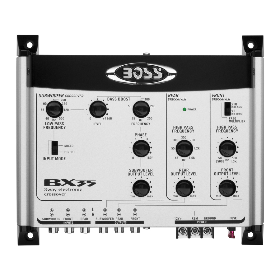
CONTROLS AND OPERATION

- Power Terminal (+12V).
- Remote Turn-On Terminal (REM).
- Ground Terminal (GND).
- Subwoofer Low Pass Frequency Control.
![]()
- Bass Boost Level Control (TO +18dB)
- Bass Boost Frequency Control
- Low Pass Mode Switch: Allows Low Pass Channel to receive signal from either the mix of Front and Rear inputs or from Low Pass Inputs directly (when head unit has appropriate 5th / 6th outputs.
- Variable Phase Selector Control: Use this control to select output phase for the subwoofer channel to provide best time alignment and stereo imaging.
- Subwoofer (Low Pass) Output Level Control
- LED Power On Indicator
- Rear Channel High Pass Frequency Control
- Rear Channel Output Level Control
- Frequency Multiplier Switch, Front High Pass Crossover
- Front High Pass Frequency Control
- Front High Pass Output Level Control
- Subwoofer Low Pass Channel Inputs
- Front Channel Inputs
- Rear Channel Inputs
- Subwoofer Low Pass Channel Terminals.
- Rear Channel Output Terminals.
- Front Channel Output Terminals.
- Fuse

WIRING DIAGRAM: Power Connection

- B+(12V): Connect a red wire to the car battery or other power source.
- REMOTE: Connect an orange wire to remote activating (12V DC) wire of car stereo or equalizer.
- GND: Connect a black wire to the car chassis for ground connection.
WIRING DIAGRAM: Two way (BIAMP) Operation
 Operation")
TROUBLE SHOOTING
| Symptom | Possible remedy: |
| Signal Processor does not turn on. | Check:
|
| Level of sound is low. | Check:
|
| Background noise is too high. | Check::
|
PRECAUTIONS
Enjoy your system, but use it wisely and safely!
- Never drive with the volume raised so high you cannot hear what is occuring in traffic around you.
- Be ware that repeated exposure to excessive volume levels can permanently damage your hearing!
- Keep all electronics away from moisture, dust, extreme heat or extreme vibrations.
Documents / ResourcesDownload manual
Here you can download full pdf version of manual, it may contain additional safety instructions, warranty information, FCC rules, etc.
Advertisement


Need help?
Do you have a question about the BX35 and is the answer not in the manual?
Questions and answers