The Can Converter R-56, R56-RMF Manual
- Installation instructions manual (8 pages)
Advertisement
TOOLS YOU WILL NEED

CONVERT ALL OF THESE RECESSED CAN LIGHT PRODUCTS
*MODELS NOT APPLICABLE FOR FAN SUPPORT
| Capri: | R5, CR1, CR1QP, CR1NB, CR1NBQP, R9ASIC, *CR5, *CR5QP, *PR1 |
| Elco: | R5H, EL5IC, EL5ICA, EL7IC, EL7ICA, EL7ICAT, EL7ICWA, EL7IC100, EL7IC100A |
| Elite: | B5IC, B5IC-AT, B6, B6IC, B6ICAT, B26, B26IC |
| Halo: | H5T, H5ICAT, ET500, EI500AT, H25ICAT, H7T, HI7T, H7ICT, H7ICAT, H7TNB, H7ICTNB, H7ICATNB, H27T, H27ICT, H27ICAT, ET700, ET2700, EI700U, EI700UAT, EI700AT, EI700NB, EI700ATNB, EI2700, EI2700AT |
| Jimway | C7 (H5), C7IC (H1), C7ICA (H3), HBR5000SIC (H21) |
| Juno: | IC2, IC2W, IC20, IC20N, IC20S, IC20NW, IC20W, IC21, IC22, IC22S, IC22W, IC23, IC23W, TC2, TC2S, TC2W, TC20, TC20S |
| L&C Lighting | 1106, 1107, 1008, 1110, 1128, LWSIC32 |
| Lightolier: | 1004IC, 1004ICN, 1004ICNQ, 1004ICQ, 1004SIC, 1004SICN, 1104IC, 1104ICN, 1104ICNQ, 1104ICQ, 1104SIC, 1104SICN |
| Lithonia: | L5, LC6, LCP, LU6, LUP, L7, L7X, L7XP, LICJ |
| Luminaire: | LUICT-00 |
| Nora: | *NH-26Q, *NH-27Q, NHIC-27Q, NHIC27QAT, NHIC-17/100/AT, NHIC-17QAT, NHIC-17QNBAT, NHIC-17/100/DW, NHIC-17/100/DWQAT, *NH-501Q, *NHIC-501QAT |
| Prescolite: | BX5, IBX5, IBX5S, IBXHW, IBXS, FT5, FT6, SCIBX |
| Progress: | P821-AT, P821-FB, P821-FBFC, P84-AT, P85AT, P85-FB, P85-TG, P86-TG, P87AT |
| Seohyun International: | 82-200IC |
| Thomas: | PS1, *PS3, PS5SH, PS9 |
| W.A.C.: | R5VI-ICA, R5VI-S-ICA, R6VI-ICA, R6VI-S-ICA |
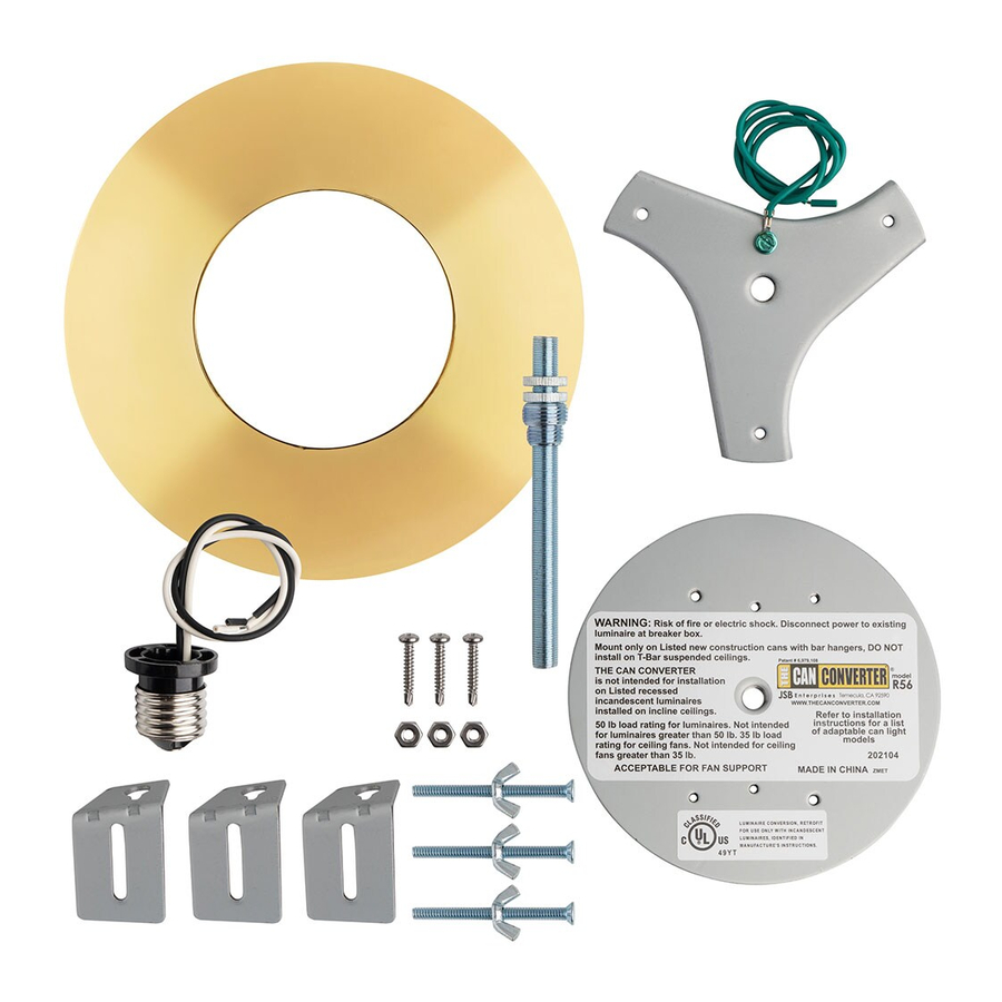
PRODUCT KIT CONTENTS

INSTALLATION

Verify proper can Installation, bar hangers must be resting on ceiling

 Turn off power at the breaker box

Use eye protection when working over your head

- Remove the light bulb and can trim from the can light you will be replacing.

- fig. A and B
Put the mounting bracket assembly together using the three offset-sliding-brackets and the three flat-head screws and wing nuts.
fig. C
If your can light housing is too narrow, use the three #10 nuts in place of the wing nuts.

- fig. A
Within the can housing, there is a metal bracket that holds the light socket. If it is adjustable, loosen the wing nut and slide the bracket to the top of the can housing. Tighten the wing nut and screw in the CAN CONVERTER power outlet adapter.
fig. B
If the socket is NOT adjustable, remove the socket from the trim and screw the CAN CONVERTER power-outlet-adapter into the socket.

- fig. A
If the screws that attach the metal can to the wall are not in a triangular configuration, remove one of the screws.
fig B
Set the assembled mounting bracket in position to use the empty screw hole. Using a CAN CONVERTER self-tapping screw, attach one of the offset-silding-brackets to the can housing.

- fig. A
Loosen the wing nuts and slide the two unattached offset-sliding-brackets so they make contact with the inside wall of the can housing.
fig. B
Mark the positions of the two empty offset-bracket holes on the can housing.

- fig. A
Loosen the self-tapping screw and remove the mounting bracket.
fig. B
Using a power drill, screw the self-tapping screws ino the marks you made. Half the length of the screw should remain exposed.

- fig. A
Re-insert the mounting bracket assembly and position the offset sliders onto the three self-tapping screws and lower the sliders onto the lock position.
fig. B
Tighten the screws securely into the can housing.

- fig. A
If the screws in your existing can ARE in a triangular configuration, remove them and replace them with the CAN CONVERTER self-tapping screws. Half the length of the screws should remain exposed.
fig. B
Use the existing holes to mount the offset-bracket assembly. Set the off-set sliders onto the three self-tapping screws and lower the sliders onto the lock position.

- Loosen the wing nuts on the flat-head screws and adjust them so that the heads are level with the base of the can. Tighten the wing nuts to lock the screws in position.


ALTERNATE INSTRUCTION PATH
Pre-assemble your new light fixture following the manufactures instructions. For chandelier installation continue to STEP 10 CHANDELIER. If you are installing a pendant, track lighting or other fixture that will be secured to a mounting plate, continue to STEP 10 PENDANT. If you are installing a ceiling fan, continue fan, continue to STEP 10 CEILING FAN.
CHANDELIER INSTALLATION
- Screw the threaded pipe into the mounting bracket until it extends below the level of the can. Screw the light hook that came with the fixture onto the threaded pipe.
*If the fixture's light hook does not fit the threaded pipe, use the reducer bushing to accommodate the diameter of the light hook.
![]()
- Place the medallion you will be using along with the chandelier's canopy against the ceiling.
Adjust the threaded pipe so that the top of the light hook threads are just inside the canopy.
![]()
- Remove the light hook, canopy and medallion. Use a brass nut to secure the threaded pipe against the mounting bracket.
![]()
- Bring your pre-assembled chandelier into position. Thread the chandelier wiring up through the links in the chain, then slide the chandelier nut, the light canopy and the medallion down the chain. Attach the chain to the light hook.
![]()


You may want to place your chandelier on a box on top of your ladder so that the chain will reach the light hook.

- Feed the wiring from the chandelier all the way up through the light hook and the threaded pipe and let the wires fall down the outside of the can. Cut off the excess wiring.
![]()
- Using wire nuts, pair together the fixture's hot wire to the power-outlet-adapter's hot wire, the fixture's neutral wire and the fixture's ground wire to the ground wire on the mounting bracket. Tuck the wiring neatly into the light canopy and medallion.
![]()
- Slide the medallion, light canopy and the light hook nut up to the ceiling. Secure the assembly in place by tightening the light hook nut onto the light hook.
(Turn your power back on at the breaker box. Your Installation is now complete)
![]()


PENDANT/FLUSH MOUNT/TRACK LIGHT INSTALLATION
- Loosen the wing nuts on the flat head screws. Place the medallion you will be using against the ceiling and adjust the length of the screws so that the heads rest about 1/16th inch inside the back of the medallion. Then tighten the wing nuts.
![]()

If you are using the flat medallion, adjust the screws so that the heads are inside the can. Then tighten the wing nuts.

- Run the wires from the power-outlet-adapter and ground wire down through the hole in the mounting bracket. Run the wires through the threaded pipe then screw the pipe into the mounting bracket.
![]()
- Place your medallion at the can light opening against the threaded pipe. Screw the pipe upward so that it extends beyond the medallion by 1/4 inch.
![]()
- Remove the medallion. Screw the brass nut onto the threaded pipe all the way up to the mounting bracket and tighten the brass nut.
![]()
- Match the correct screw holes in the CAN CONVERTER mounting plate with the holes in the new fixture's canopy. Screw the fixture's long screws into the holes in the mounting plate.
Note: The screw heads will be on the inside of the can.
![]()


If you are installing a flash mounted fixture, match the long screws to the correct holes in the mounting plate. The long screws will screw in from the bottom up through the canopy.

- Screw the mounting plate onto the threaded pipe so that the plate rests against the heads of the screws on the mounting bracket.
![]()
- Thread the second nut through the wires. Screw the brass nut up the threaded pipe all the way to the mounting plate. Tighten the brass nut to secure the mounting plate to the threaded pipe.
![]()
- Bring your fixture and medallion to the can light. Cut off any excess wiring.
![]()
- Using wire nuts, pair together the fixture's hot wire, to the power-outlet-adapter's hot wire, the fixture's neutral wire to the power-outlet-adapter's neutral wire and the fixture's ground wire to the power-outlet-adapter's neutral wire. Tuck all of the wiring into the fixture's canopy.
![]()
- Raise the medallion, the light canopy and fixture to the ceiling. Secure the canopy by attaching the fixture's decorative nuts to the extending screws. Alternatively drive the nuts to the fully tightened position. The screws will back drive then stop when they are tightly in place.
(Turn the power back on at the breaker box. Your Installation is now complete)
![]()


CEILING FAN INSTALLATION
- Loosen the wing nuts on the flat head screws. Place the medallion you will be using against the ceiling and adjust the length of the screws so that the heads rest about 1/16th inch inside the back of the medallion. Then tighten the wing nuts.
![]()

If you are using the flat medallion, adjust the screws so that the heads are inside the can. Then tighten the wing nuts.

- Run the wires from the power-outlet-adapter and ground wire down through the hole in the mounting bracket. Run the wires through the threaded pipe then screw the pipe into the mounting bracket.
![]()
- Place your medallion at the can light opening against the threaded pipe. Screw the pipe upward so that it extends beyond the medallion by 1/4 inch.
![]()
- Remove the medallion. Screw the brass nut onto the threaded pipe all the way up to the mounting bracket and tighten the brass nut.
![]()
- Screw the mounting plate onto the threaded pipe so that the plate rests against the heads of the screws on the mounting bracket. Thread the second nut through the wires. Screw the brass nut up the threaded pipe all the way to the mounting plate. Tighten the brass nut to secure the mounting plate to the threaded pipe.
![]()
- Raise the medallion up to the ceiling, followed by the fan hanger bracket. Run the power-outlet-adapter wires and ground wire through the side of the fan hanger bracket. Using the long screws supplied with your fan, screw the fan hanger bracket to the appropriate holes in the mounting plate.
![]()
- Lift the fan and capture its ball joint in the fan hanger bracket. Cut off any excess wiring.
![]()
- Using wire nuts, pair together the fixture's hot wire, to the power-outlet-adapter's hot wire, the fixture's neutral wire and the fixture's ground wire to the power-outlet-adapter's neutral wire. Capture the wiring inside the fan canopy.
![]()
- Raise the fan canopy to the fan hanger bracket. Secure the canopy in place by using the two canopy's attachment screws.
(Turn the power back on at the breaker box. Your installation is now complete)
![]()


WARNING

RISK OF ELECTRICAL SHOCK. Disconnect the the existing luminaire at the breaker box. The luminaire's wiring, ballasts or other electrical parts may be damaged when drilling for installation of the reflector kit hardware. Check for damage to the enclosed wiring and components. Do not alter, relocate or remove wiring, lamp holders, ballasts or any other electrical components. Install this kit only in luminaires that have the construction features and dimensions shown in the photographs and Ior drawings. To prevent wire damage, do not expose wiring to the sheet metal of the can or other sharp objects. The Can Converter is not intended for installation on listed recessed incandescent luminaires installed on an inclined ceiling. Mount only on listed new construction cans with bar hangers. DO NOT install on T-bar suspended ceilings. This product is intended for luminaires with 50 lb. ratings or less. It is not intended for luminaires greater than 50 lbs. It is not intended for ceiling fans with load ratings of greater than 35 lbs. The reflector kit requires knowledge of lighting luminaire's electrical systems. If not qualified, do not attempt installation. Contact a qualified electrician
This product is designed to work with cans that utilize incandescent bulbs.
Customer support is available Monday through Friday 9:00am to 5:00pm PST at 866-409-9634
JSB Enterprises
Temecula, CA92590
www.thecanconverter.com
Documents / Resources
References
Download manual
Here you can download full pdf version of manual, it may contain additional safety instructions, warranty information, FCC rules, etc.
Advertisement

Need help?
Do you have a question about the R-56 and is the answer not in the manual?
Questions and answers