Advertisement
- 1 COMPONENTS NAME
- 2 PRODUCT SPECIFICATION
- 3 USE TIPS
- 4 HOW TO DEFINE THE VALUE OF MARCHING DIRECTION
- 5 HOW TO FOLLOW THE VALUE OF THE MARCHING DIRECTION YOU DEFINED
- 6 MAP ORIENTATION
- 7 LET'S DEFINE THE MARCHING DIRECTION ON THE MAP
- 8 LET'S DEFINE OUR POSITION ON THE MAP
- 9 LET'S USE THE CLINOMETER
- 10 HOW TO ESTIMATE THE DISTANCE TO THE OBJECT BY THE MAP
- 11 THE HEIGHT OF AN OBJECT
- 12 HOW TO MEASURE THE ANGLE
- 13 HOW TO MEASURE THE DISTANCE ON THE GROUND
- 14 MEASURE OF THE DISTANCE OF AN OBJECT, THE HEIGHT AND/OR WIDTH OF WHICH ARE KNOWN
- 15 MEASURE THE DISTANCE WITH SCALE-MARKED GLASS
- 16 WARNING!
- 17 CONTACT US
- 18 Documents / Resources
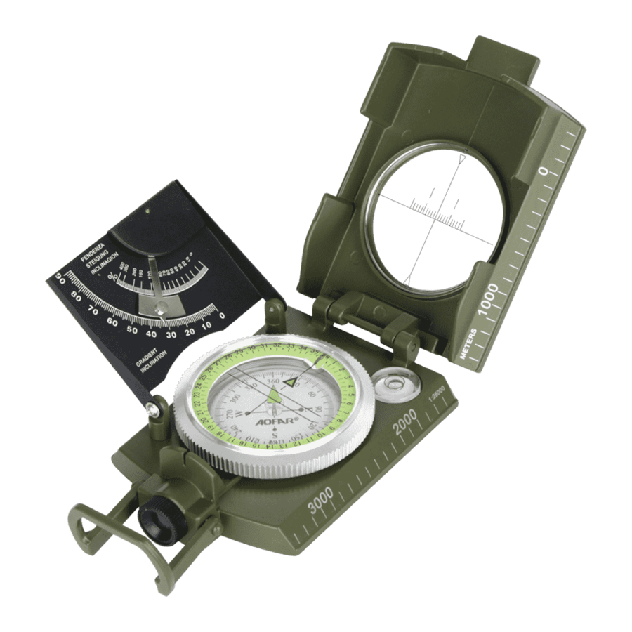
COMPONENTS NAME

- Lid
- Reading Lens or Prism
- Window with Aiming line
- Hinge
- Scale (Centimeter Ruler on opposite side)
- Tripod Connection
- Spirit level
- Glow-in-the Dark Arrow No1
- 360° Rotating Bezel Ring
- Glow-in-the Dark Arrow No2
- Clinometer
- Glow-in-the Dark Circle (Fixed tip point)
- 360°compass card
- Holding Ring
- Aiming Point
- Sighting Lens with Adjustable Diopter (Thermoelastic Liquid-Filled Capsule with Floating Dial)
- Heavy-duty zinc Die-Cast
- Conversion chart: Angle/Gradient/Distance
- Distance-measuring notches
PRODUCT SPECIFICATION
The compass consist of a Zinc alloy housing and a metal lid (1) with a glass window which the Aiming line etched into it. The Window (2) is mounted in the lid (1) with a robust hing that can be turned through 180°. This allows the Window to be moved into reading position and be folded back after use.
The compass is provided with a clinometer enabling you to measure slopes and gradients in degree or in percent. The compass is provided with an integrated spirit level (7). It can be screwed on a tripod (at the back) that means often threaded fitting in the base and serve as theodolite for simple terrain surveys.
- Model AF-4074 T
- Color Army green
- Size 100x66X31mm
- Dial diameter 50mm
- Weight 287g
- Material Zinc alloy
- Clinometer Yes
- Waterproof Yes
- Luminous Yes
This lens system (16) being provided with an integrated index line and an excellent magnifier allows extremely precise reading. Problems inevitably caused by mirror reading and potential parallax errors are eliminated by prismatic reading.
Excellent damping of the dial system ensures rapid and precise reading to the fraction of a degree.
USE TIPS
Move the the lid (1), adjust the lid either up or down until the Aiming Point (15), aiming line (3) and the object on a straight line. While doing so keep the compass exactly horizontal by using the integrated spirit level (7).

By skillfully handing the compass the Arming line (3) corresponds to the Aiming Point (15), thus ensuring that eyes, compass dial and object are at same level and resulting in utmost accuracy. This method allow to read the fraction of an angular degree.
Adjust the position of the prism or lens which on the 360° Rotating Bezel Ring (9 ) until you see distinctly the numbers of the compass card (13 ). In models with adjustable eyepiece, the Sighting Lens (16) must be rotated until numbers in degree are clearly visible. Optimal results are obtained when you keep the compass at a distance of 1-2cm from your eyes.
HOW TO DEFINE THE VALUE OF MARCHING DIRECTION
With your compass in reading position, aim at an object, sighting it through the Aiming Point (15 ) and the aiming line (3). Now read the value of your marching direction on the compass card (13 ) which also correspond to the azimuth of the object.
HOW TO FOLLOW THE VALUE OF THE MARCHING DIRECTION YOU DEFINED
If the value of the marching direction is known, look at the compass card (13) and turn around until said value appears on the graduated dial.
MAP ORIENTATION
For more complicated operations to be camied out on the topographic map, it is necessary to orientate the geographic north of the map with that magnetic of the earth.
Place the compass on the map. Align the centimeter-marked line (5) with that meridian closest to your position, so that the upper lid (1) points to the north of the geographic map. Meridians are parallel lines running from the upper to the lower part of the map.
Holding the compass in position, rotate the map until the north-seeking needle (10) on the dial coincides with the index line of the Glow-in-the Dark Circle (12). The map is now oriented with the ground.
LET'S DEFINE THE MARCHING DIRECTION ON THE MAP
- After you aligned you map with the north pole (the description in MAP ORIENTATION), draw a line on the map starting from you position to your final destination.
- Place the compass on the map with one contact edge along the line which is running from your own position to the objective. the compass lid indicates the direction of the objective.
- Read the value of marching direction on the compass card (13) which corresponds to the index line of the Glow-in-the Dark Circle (12).
- Remove the compass from the map, look at the compass card (13) and turn around until the value of your marching direction (defined as described point C )
- Find an auxiliary destination point which must be on the same survey line and start following it.
- Repeat this operation until you reach your final destination.
The longer your route, the more you have to repeat the above operation which will help you keep the direction you defined.
LET'S DEFINE OUR POSITION ON THE MAP

Select two well visible points on the ground and mark them on the map. Once the map is orientated (operated as MAP ORIENTATION), with your compass measure the value in degree of position (A) and draw a line on the map in accordance with said value. Now pass through point (B).
LET'S USE THE CLINOMETER
The clinometer is an instrument allowing the measuring of differences in height and slopes. It can be pendular or automatic.
Open the compass, adjust the Clinometer (11), until it is perpendicular to the case (17). Aim at the upper (or inferior) edge of your target by the Aiming line (3) (inferior side), Pay attention as to create one single line. The more your tilt the your compass, the more the clinometer changes its position. Aim at the target and tilt the compass on the clinometer side so that the pendulum stops and read the angle of inclination.
If the object be located inferiorly to the observer, simply turn the compass until the hinge (4) points to you, aim at it by viewing through the upper part of the lid and proceed in accordance with the above mentioned instructions.
Table 2
| Ⅰ Angle 0-360 | Ⅱ Angle 0-4600 | Ⅲ Angle 0-400 | Ⅳ Gradient % | Ⅴ width/distance |
| 1 | 18 | 1 | 2 | 1/60 |
| 2 | 35 | 2 | 3 | 1/30 |
| 3 | 53 | 3 | 5 | 1/20 |
| 4 | 71 | 4 | 7 | 2/30 |
| 5 | 89 | 5 | 9 | 7/80 |
| 6 | 107 | 6 | 10 | 1/10 |
| 7 | 125 | 8 | 12 | 1/8 |
| 8 | 142 | 9 | 15 | 1/7 |
| 10 | 178 | 11 | 18 | 1/6 |
| 12 | 219 | 13 | 21 | 1/5 |
| 14 | 250 | 16 | 25 | 1/4 |
| 17 | 302 | 19 | 30 | 3/10 |
| 18 | 320 | 20 | 33 | 1/3 |
| 20 | 355 | 22 | 36 | 3/8 |
| 22 | 391 | 25 | 40 | 2/5 |
| 24 | 426 | 27 | 45 | 4/9 |
| 27 | 480 | 30 | 50 | 1/2 |
| 31 | 551 | 36 | 60 | 3/5 |
| 34 | 604 | 38 | 66 | 2/3 |
| 35 | 622 | 39 | 70 | 7/10 |
| 37 | 658 | 41 | 75 | 3/4 |
| 40 | 711 | 45 | 84 | 5/6 |
| 42 | 747 | 47 | 90 | 9/10 |
| 45 | 800 | 50 | 100 | 1/1 |
| 50 | 889 | 56 | 120 | 1+1/5 |
| Ⅰ Angle 0-360 | Ⅱ Angle 0-4600 | Ⅲ Angle 0-400 | Ⅳ Gradient % | Ⅴ width/distance |
HOW TO ESTIMATE THE DISTANCE TO THE OBJECT BY THE MAP
Measure the distance to the object on the map by Centimeter Ruler (5), Multiply the scale of the map.
Map Scan: 1: 25000
Distance (M) =Distance (mm) on the map X 25000÷1000
Map Scan: 1: 50000
Distance (M) =Distance (mm) on the map X 50000÷1000
THE HEIGHT OF AN OBJECT

You can measure or estimate the distance to the object on the map (see previous chapter).
Multiply this distance by the factor indicated in column IV or V (Table 2) (whichever is easier for you), referring to the angle in column I measured with the clinometer (the description in LET'S USE THE CLINOMETER).
The above mentioned example is based on an angle of 14 and a distance of 2000m.
2000m X 25% column IV (Table 2) /100% =500m
OR 2000m X 1/4 column V (Table 2)=500m
HOW TO MEASURE THE ANGLE
Measure the right side of the object. Keeping in mind the value in degree that you defined, slowly orientate the compass towards the left side of the object. From the first value in degree deduct the second value you just defined. The difference represent the value in degree of the angle between the left and right sides of the object.
 N. B: Measure of the angle through the north. If the value 360° (north) come across the direct line on the Glow-in-the Dark Circle (12) during your measuring operation, consider 360°=0°. The calculation will be 360°-second value in degree +first value in degree.
Example:
If the first value in degree is 4 and the second is 354, the angle will be 10. (360-354+4=10).
HOW TO MEASURE THE DISTANCE ON THE GROUND
In accordance to the principle mentioned in the previous tree chapters, it is possible to define the distance on the ground between two well-visible points on the ground.
For example, you can measure the width of a farm house, the length of a bridge, etc.
There is one necessary condition to measure the distance from your own position to that of the object: the line running from these two positions must be as perpendicular as possible to the side of the object to be measure
Example:

At a distance of 4000m, a bridge spans a river, transverse to the line of vision. How long is the bridge if an angle of 6°is measured from the right to the left river bank?
6°=10% or 1 /10
4000x10%=400m OR 4000X1 /10=400m
MEASURE OF THE DISTANCE OF AN OBJECT, THE HEIGHT AND/OR WIDTH OF WHICH ARE KNOWN
If the height or width of an object is known or drawn from a map, it's distance will be defined by simply inverting the calculation mentioned above the description in previous chapter.
In other words, if the width of an object with an angle of 8, is 1/7 of the distance according to the table 2, the same will be reverse case, the distance is 7 times wider than the width or height.
Example 1:
A TV-tower is visible in the field and its height is known to be 200 m. The angle measured with the clinometer is 7° from bottom to top of the tower. Column IV (gradient in %) indicates 12% for 7°.
100% X 2000m (height of object) / 12% (column IV (Table 2) ) =1600m
OR 200m x 8 (inversion of 1/8) =1600m
Example 2

The angle measured between object B and C (see figure) is 34°. The distance between B and C is 5 km according to the map column IV, Table 2 indicates 66%.
100% X 5 km / 66%=7. 5km
OR 5km X 3/2 = 7. 5km
When using this method, the object of known width must be perpendicular to the line of sight.
MEASURE THE DISTANCE WITH SCALE-MARKED GLASS

- Aiming line
- Horizontal line with measuring notches
- Measuring line
- First object
- Second object
The glass cover with the aiming lines, is provided with notches which allow you to measure the distance from an object when the distance between the target and another visible object on the same level of the observer on the horizontal line of the glass.
10 notches is 0. 9cm, each notch is 1/9cm, the distance between eyes and the Aiming line is 12cm.
For example, if the distance between two objects is 36m and the notches on the glass are 12.

400m is the distance between you and the object.
The simple formula is

Of course, if the distance between two objects is 36m, and and the notches on the glass are 12, and the other object is some distance from you on the same level, and the notch is 18.
36/12*18=54m
WARNING!
In superior quality compass the oscillation of the needle is stabilized by the liquid in which it is totally dipped (13). Strong variations in temperature or pressure can cause the formation of small air bubbles around the compass card (13) . These bubbles do not interfere with the compass functioning and they will disappear in 24-48 hours under normal temperature conditions .
Avoid anyhow to use the compass at temperatures much under 0° centigrade.
Make sure to be always far from magnetic fields created by iron parts, magnetic cores or electric wires which cause the compass to show wrong values.
Prevent your instrument from falling or getting damaged and never tamper it (so as to keep your guarantee always valid)
CONTACT US
service@aofar. com
URL: www.aofar.com
Documents / Resources
References
Download manual
Here you can download full pdf version of manual, it may contain additional safety instructions, warranty information, FCC rules, etc.
Advertisement


Need help?
Do you have a question about the AF-4074 and is the answer not in the manual?
Questions and answers