
Subscribe to Our Youtube Channel
Related Manuals for Nu-Flame Ellesse-R LS800

Summary of Contents for Nu-Flame Ellesse-R LS800
- Page 1 Ellesse-R - Electric Fire Range Operating Instructions for the Remote-Control Handset Rev 3- 03.24...
- Page 2 MADE IN BRITAIN Thank you for purchasing your Nu-Flame electric fire! Your choice has directly supported British manufacturing and jobs: all our fires are responsibly and ethically designed, manufactured and tested by us in our state-of-the-art factory in Surrey.
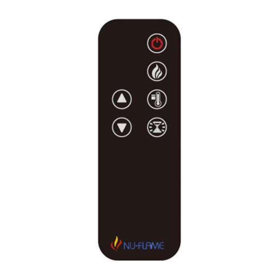
- Page 3 remote-control handset digital information screen...
-
Page 4: Power On And Off
power on & off • The current room temperature ℃ will be displayed on the digital information screen for 20 seconds when the appliance is switched on by the remote-control handset. Switch on the mains power to the appliance. Switch on the on/off rocker switch and the appliance will emit an audible beep. On/Off rocker switch is tucked away at the top of the front glass panel, behind the surround or face of fire cutout... -
Page 5: Heating Function
heating function Do not leave the appliance unattended when the heater is operating! • When the heating function is selected the thermostat will continually monitor the room temperature and automatically control the operation of the heater fan to maintain the set temperature. •... -
Page 6: Timer Function
timer function • This function allows you to set the time until the appliance switches off automatically. • When the selected timer finishes all lighting and heating will automatically switch off. • When adjusting the timer function the selected setting will flash for 5 seconds before being set; the ℃... -
Page 7: Problem Solving
• Set timer function to 0 hours (0H). Notes ___________________________________________________________________ ___________________________________________________________________ ___________________________________________________________________ ___________________________________________________________________ ___________________________________________________________________ ___________________________________________________________________ nu-flame ltd . unit 4 kimpton trade & business centre . minden road . sutton . surrey . sm3 9pf 020 8254 6802 www.nu-flame.co.uk technical@nu-flame.co.uk... -
Page 8: Duplicate Data Plate
The data plate for the fire is within the fire casing and is only accessible by a properly qualified person. For your convenience a duplicate data plate is below. Please keep this information safe as it will be required if you need to contact Nu-Flame for any reason regarding your fire. Doc Ref: 01.24... -
Page 9: Safety Warnings
SAFETY WARNINGS • This appliance can be used by children aged from 8 years and above and persons with reduced physical, sensory or mental capabilities or lack of experience and knowledge if they have been given supervision or instruction concerning use of the appliance in a safe way and understand the hazards involved. -
Page 10: Installation Instructions
INSTALLATION INSTRUCTIONS 1) The appliance must be earthed. 2) Only for indoor use and not to be installed adjacent to a bath, shower or swimming pool. 3) We recommend hard wiring via a 13 amp, 240 volt switched fused spur positioned accessible and adjacent to the fire. - Page 11 Ellesse-R Electric Fires purchase via our authorised dealer network can have the guarantee extended by an extra year by registering online at www.nu-flame.co.uk/electric-fires-warranty within 30 days of purchase. The guarantee does not cover reimbursement of any third-party repair or replacements costs, nor does it cover compensation or consequential losses.
- Page 12 Dimensions & Weights Dimensions in millimetres Model Weight kg LS800 Landscape PR800 Portrait LS1200 Landscape 1281 1313 LS1700 Landscape 1705 1737 Nu-Flame Multitool Hook for removing front trim For glass brackets For adjusting feet Doc Ref: 01.24 Page 5...
- Page 13 INSTALLATION AND REMOVAL OF THE FRONT GLASS PANEL Disconnect from power supply before removing glass Normally the only reason you would have to remove the glass would be to lay he fuel bed and log set on installation To remove the front glass, you will first need to remove the 3 black steel trims as shown in the photo below. There is a small hole in the end of the longer trim that runs along the front of the glass.
- Page 14 The glass panel is seated in channel at the top and it stands on a ledge at the bottom. Both run the full width of the fire. Once the suction cups are securely attached to the glass panel you need to lift the glass up, off the ledge and then slowly allow the panel to drop in front of the bottom ledge and the 8mm nuts.
- Page 15 FUEL BED AND LOG LAYOUT Once the glass is removed and safely put to one side, you can proceed to setting up the fuel bed and the log set. The fuel bed needs to be laid first and the process is the same regardless of which size fire you have. Fuel Bed Layout The textured acrylic base will support the fuel bed material.
- Page 16 Log Set Layout Once the fuel bed is laid the main log set can be put in place. There are 3 log sets, depending on which size fire you have. They are the 800L / 800P, the 1200L and the 1700L. The log set has been designed to lay on the fire as shown in the following photos.
- Page 17 Final Adjustment of Log Set & Fuel Bed Some of the small, completely charred, logs have a unique profile and should be placed with the overhang at top facing forward. This provides a flat surface at the front which reflects the lighting form the underbed: Overhang at the top facing forward Flat surface to reflect underbed lighting...
- Page 18 Fixing Fire To Wall & Levelling Up Option 1 - Use all 4 adjustable rear brackets Option 2 - Use top 2 rear brackets and sit fire on the 4 adjustable feet Minimum 10mm clearance behind strengthening 4 # Adjustable Wall Brackets (No need to use if feet are screwed)
- Page 19 Side Panel Setup The fire comes with both options fitted. Undo the 7 screws and remove the option not required. Option A Glass sided. For installations where fire is viewable from one or both sides (in addition to the front). Option B Blanking Panel.
- Page 20 Doc Ref: 01.24 Page 13...
- Page 21 Doc Ref: 01.24 Page 14...
- Page 22 The preceding pages refer to all installations The following pages detail the installation requirements for specific applications: Hole in the Wall, Media Wall, Fireplace Installation etc Doc Ref: 01.24 Page 15...
- Page 23 INSTALLING THE ELLESSE-R ELECTRIC FIRE WITH WARWICK SUITE OR LANCASTER SUIT TO A BRICK WALL If the wall is not strong enough to support the fire consider floor mounting instead 1. Fit the bottom support angle to the wall whilst ensuring it is perfectly level. 10 x 2” countersunk screws and plastic wall plugs are supplied, requiring a 7mm masonry drill.
- Page 24 Warwick LS800 Fireplace Note: Lancaster LS800 Dimensions are the same, except the 103mm high ‘under plinth’ is not present on the Lancaster Warwick LS1200 Fireplace Note: Lancaster LS800 Dimensions are the same, except the 103mm high ‘under plinth’ is not present on the Lancaster Doc Ref: 01.24 Page 17...
- Page 25 INSTALLING THE PR800 ELLESSE-R ELECTRIC FIRE WITH A BALMORAL SUITE 1. The front glass area of the Ellesse-R PR800 is designed to fit the opening in the Balmoral Suite back panel with minimal, but adequate, clearance 2. The surround is only rebated by 65mm so the Ellesse-R PR800 will have to be installed within the wall or studwork.
- Page 26 ONE SIDED - FULLY RECESSED INSTALLATION Dimensions for opening in millimetres Model Feet Centres LS800 Landscape minimum LS1200 Landscape 1320 1226 minimum LS1700 Landscape 1744 1650 minimum Fire to be positioned into studwork prior to cladding with 12.5mm plaster board. Note: We recommend a solid base board for the 4 feet of the fire to sit on.
- Page 27 CORNER INSTALLATION (FRONT & 1 SIDE VISIBLE) Dimensions for opening in millimetres Model Feet Centres LS800 Landscape minimum LS1200 Landscape 1301 1226 minimum LS1700 Landscape 1725 1650 minimum Fire to be positioned into studwork prior to cladding with 12.5mm plaster board. Note: We recommend a solid base board for the 4 feet of the fire to sit on.
- Page 28 THREE-SIDED INSTALLATION (FRONT BOTH SIDES VISIBLE) Dimensions for opening in millimetres Model Feet Centres LS800 Landscape minimum LS1200 Landscape 1289 1226 minimum LS1700 Landscape 1713 1650 minimum Fire to be positioned into studwork prior to cladding with 12.5mm plaster board. Note: We recommend a solid base board for the 4 feet of the fire to sit on.
- Page 29 HOLE IN THE WALL INSTALLATION WITH DELUXE TRIM Dimensions for opening in millimetres Model Feet Centres LS800 Landscape minimum LS1200 Landscape 1320 1226 minimum Studwork faced with Line up front lip on fire 12.5mm plasterboard with front of plasterboard and put a screw in each foot Minimum 10mm gap Trim held on...
Need help?
Do you have a question about the Ellesse-R LS800 and is the answer not in the manual?
Questions and answers