
Summary of Contents for EN-KO Electronics CCS 4.2
- Page 1 EN-KO Electronic Control Systems Ltd. CCS 4.2 CCS 4.2 COMPRESSOR CONTROL PANEL User Manual CCS 4.2 User Manual 1/48...
-
Page 2: Table Of Contents
EN-KO Electronic Control Systems Ltd. CCS 4.2 1- CCS 4.2 INTRODUCTION............................3 2- SYSTEM DEFINITION ..............................3 2 – 1 Start-up Screen ............................4 2 –2 Home Screen .............................. 5 2 – 3 Settings Menu Screen ..........................8 2 – 4 Alarm List Screen ............................8 2 –... -
Page 3: 1- Ccs 4.2 Introduction
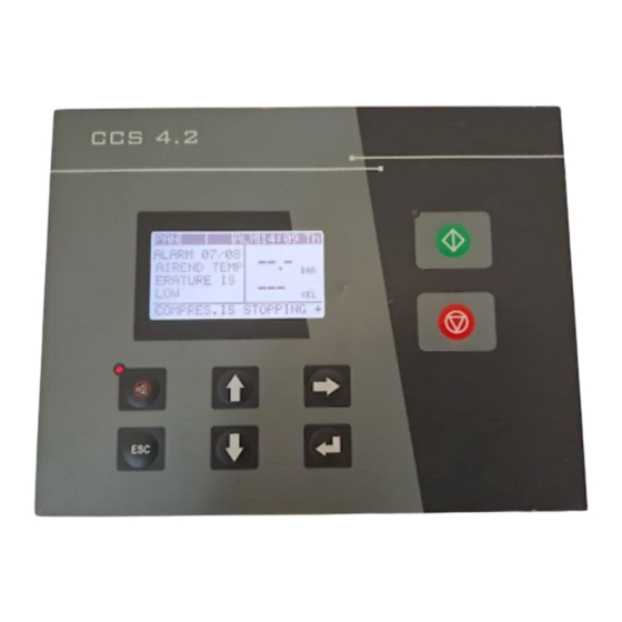
1- CCS 4.2 INTRODUCTION CCS 4.2 is designed for screw type air compressors. The unit is a microcontroller based air compressor controller which starts/stops the compressor regulates the air pressure, checks the temperature levels, protects the compressor against failures in the system and provides energy saving through variable speed control. All the inputs/outputs and the user interface is combined in a single unit. -
Page 4: Start-Up Screen
This button is used to go to the sub-menu page or exit the Parameter Edit page with saving the parameter. Note: If the Up Scroll and Down Scroll buttons are pressed simultaneously for 3 seconds, the CCS 4.2 enters the Service Mode. -
Page 5: Home Screen
In an Inverter compressor system, the compressor will be in this status during the time until the motor reaches the optimum CCS 4.2 User Manual 5/48... - Page 6 This screen is accessed by pressing the down scroll button once while in the home screen. The user can see how much time is left until the next maintenance for various parts. The air pressure is indicated on the info banner instead of the real-time clock. CCS 4.2 User Manual 6/48...
- Page 7 & time info screen. Various network related information can be viewev from this screen. Please ensure the Ethernet module parameter is set correctly Figure 8 – Ethernet Info Screen from Factory Parameters -> Ethernet Module Yes/No. CCS 4.2 User Manual 7/48...
-
Page 8: Settings Menu Screen
If the enter button is pressed while the cursor is over an alarm, the user will be prompted to reset the alarm, the reset process can be completed by pressing the enter button again or can terminate the alarm reset process by pressing the ESC button. CCS 4.2 User Manual 8/48... -
Page 9: Pressure Calendar Screen
The user can set the device language, contrast ratio and device information, which contains info about software, firmware and bootloader version. In order to set the language or contrast ratio the user will need to enter a password. Figure 13 – Controller Settings Screen CCS 4.2 User Manual 9/48... -
Page 10: Date/Time Settings Screen
The CC field is optional so it can be left blank or email addresses that are desired to be CC’ed can be entered here. The username and password is to be entered in their respective fields if the e-mail ID confirmation option is set to “yes”. CCS 4.2 User Manual 10/48... -
Page 11: Inputs & Outputs
** : The Emergency Stop function on the IN0 input is non-configurable and can not be changed. The connection diagram for the CCS 4.2 inputs is shown below. The COMMON input is short-circuited with GND input inside the control unit. -
Page 12: Analog Inputs
KTY R25=1K KTY R25=2K PT1000 PT100 Open-Circuit Voltage 3.2V * : The number of analog inputs can be increased by upto 2 inputs using an optional ENKO extension module, which communicates over the CanBUS port. CCS 4.2 User Manual 12/48... -
Page 13: Analog Outputs
The RS485 communication port can be used for two functions. If there is an Inverter in the system, this port should be connected to the RS485 output on the Inverter. The CCS 4.2 will automatically connect to the Inverter with ModBUS Master protocol. -
Page 14: Parameter List
Ethernet Module Yes / No Constant Variable Analog Speed Control Source Constant Soft Start Mitsubishi FR-F,FR-AF Mitsubishi FR-E Mitsubishi Leroy Somer Inverter Trademark FR-F ABB ACS500,ACS800 AN1 Sensor Maximum Value 99.9 AN2 Sensor Maximum Value 99.9 CCS 4.2 User Manual 14/48... - Page 15 2 Poles 8 Poles PI Parameters Default Minimum Maximum Unit Maximum Speed 3000 10000 Minimum Speed 1500 2900 Optimum Speed 2700 3000 Speed at Unload 1800 3000 P Factor I Factor Maximum Ramp Value Seconds CCS 4.2 User Manual 15/48...
- Page 16 AN3 Temperature Offset Degrees AN4 Temperature Offset Degrees AN7 Temperature Offset Degrees AN8 Temperature Offset Degrees ANOUT0 Offset -0.5 0.5 Miliampers ANOUT0 Value 25 Miliampers Ethernet Parameters Default Minimum Maximum Unit MAC Adress IP Address CCS 4.2 User Manual 16/48...
-
Page 17: User Parameters
The maximum value of this parameter is Air End Pressure Alarm Value minus the Minimum Regulation Difference. The minimum value of this parameter is 0.2 bars lower than the Unload Pressure. The minimum value of the Unload CCS 4.2 User Manual 17/48... - Page 18 Getting Stop Delay (sec): This timer determines how much delay there will be between pressing the Stop Button on the CCS 4.2 panel and the stop of the compressor. After the Stop Button is pressed and this delay timer is still counting, the user can press the Start Button to cancel the stop operation and this timer will be reset.
-
Page 19: Service Parameters
Airend Pressure Initial Value (bar/psi): If the airend pressure is above this parameter during the initial start of the compressor, the CCS 4.2 will output an “Air is Not Draining“ alarm. When the airend temperature drops below this value, the “Air is Not Draining“ alarm will automatically be reset. - Page 20 Pressure Difference Failure Delay (sec): If the pressure difference between the airend pressure and line pressure exceeds the warning or alarm limits, the CCS 4.2 will indicate a warning or alarm at the end of the time period determined by this parameter value.
-
Page 21: Factory Parameters
4 – 3 Factory Parameters Ethernet Module Yes / No: If theres an Ethernet module connected to the CCS 4.2 and this parameter is set to Yes, then the Ethernet functions can be done. If this parameter is selected as No, then the Ethernet functions cannot be done. - Page 22 (FR-F and FR-E), Leroy Somer (PowerDrive and Digi Drive) and ABB (ACS500 and ACS800) models are currently supported by the CCS 4.2 and new models are being added so please check with the manufacturer for updates. CCS 4.2 User Manual...
- Page 23 The minimum value for this parameter is No, maximum value is Yes and the default value is Yes. Extention Unit Yes / No: If the digital inputs / outputs or the analog inputs / outputs on the CCS 4.2 controller are not enough, a CCS 4.2E extention unit can be connected to the controller in order to increase the I/O’s.
-
Page 24: Communication Parameters
Data Bits: This parameter determines the number of data bits of the RS232 communication port. The minimum value for this parameter is 7 bits, the maximum value is 8 bits and the default value is 8 bits. CCS 4.2 User Manual 24/48... -
Page 25: Rs485 Parameters
The minimum value for this parameter is 1, maximum value is 255 and the default value is 1. Incoming Data Timeout (mSec): This parameter determines how long the CCS 4.2 will wait to receive an incoming data before being timeout when the RS485 port is being used to communicate with the Inverter. -
Page 26: Ethernet Parameters
MAC Address: This parameter determines the MAC address for the CCS 4.2. IP Address: This parameter determines the IP address for the CCS 4.2. If the Automatic / Manual IP Getting parameter is set as Manual, the address entered in this parameter is highly important. -
Page 27: Alarm Parameters
The minimum value for this parameter is 50 C, maximum value is 150 C and the default value is 105 4 – 6 Alarm Parameters CCS 4.2 User Manual 27/48... - Page 28 The minimum value for this parameter is 0 bars, maximum value is 15.8 bars and the default value is 8.5 bars. Temperature 1 Upper Value (C/F): If the Temperature 1 value exceeds the limit set by this parameter, the controller will stop the motor and display a warning. CCS 4.2 User Manual 28/48...
-
Page 29: Calibration Parameters
C, maximum value is 5 C and the default value is 0 AN8 Temperature Offset (C/F): If there is an I/O extension unit connected to the CCs 4.2, this parameter calibrates the variance of the AN8 temperature input. CCS 4.2 User Manual... -
Page 30: Logo Settings
Return Factory Parameters: If the factory has done the Save Factory Settings operation after the initial parameter configuration of the CCS 4.2 panel, all the parameters can be restored back by using this option. Please note that all the current parameter settings will be replaced by the factory set parameters. - Page 31 The Motor Nominal Power and Motor Nominal Current values set on the Inverter are multiplied with this parameter and sent to the Inverter from the CCS 4.2. The minimum value for this parameter is 0.5, maximum value is 1.5 and the default value is 1.
-
Page 32: Pi Parameters
This set of parameters will only appear if the Speed Control Source parameter is set to Variable or Analog. Boost (%): This parameter determines how much boost voltage will be applied to the Inverter output during initial motor ramp up so that the torque stays constant. CCS 4.2 User Manual 32/48... - Page 33 The minimum value of this parameter is 0, maximum value is 200 and the default value is 110. Soft-PWM Operation Selection (P240): This parameter only applies to Mitsubishi branded Inverters. Soft-PWM Operation Selection determines the noise of the motor. CCS 4.2 User Manual 33/48...
-
Page 34: Preheat Parameters
The minimum value of this parameter is 0: NO, maximum is 1: YES and the default value is 1: YES. 4– 14 Preheat Parameters The Preheat Parameters group is only active on CCS 4.2’s where the customer code is 1000. Preheat Yes / No: This parameter determines wether the preheat function is active or not. -
Page 35: Alarm / Warning Descriptions
Oil Filter Closed: If the signal from the Oil Filter input fails this alarm is signaled. Please check the oil filter. Auxiliary Failure – 1: If a signal is received at the Aux 1 input of the CCS 4.2, this alarm is signaled. Please check the hardware that is connected to the Aux 1 input. - Page 36 Auxiliary Failure – 2: If a signal is received at the Aux 2 input of the CCS 4.2, this alarm is signaled. Please check the hardware that is connected to the Aux 2 input. Auxiliary Failure – 3: If a signal is received at the Aux 3 input of the CCS 4.2, this alarm is signaled. Please check the hardware that is connected to the Aux 3 input.
- Page 37 CCS 4.2 does not receive a feedback that it is energized within 5 seconds, this alarm will be signaled. Main Motor Contactor Didn’t Leave : If any one of the inputs on the CCS 4.2 is set as Main Feedback and main motor contactor feedback is received, the CCS will start checking the contactor for failures.
-
Page 38: Warinings That Do Not Stop The Motor
5-1-2 Warinings that do NOT Stop the Motor Air Filter is Plugged: If the signal is lost from the CCS 4.2 Air Filter input, this warning will be signaled. Please check the air filter. Pressure Difference is High: If the line pressure is higher than 6 bars, and the pressure difference between the line and the airend is larger than or equal to the limit set by the Pressure Difference Alarm Value Value parameter, this warning is signaled. -
Page 39: Inverter Unit Alarms / Warnings
Inverters, the connection between MRS and PC is the output cut-off ports. If during normal operation this input is cut, the Inverter will cut off its output. The CCS 4.2 will check this input as a security measure during initial start-up. If this input has not changed its status, this alarm will be signaled. -
Page 40: Inverter Warnings That Do Not Stop The Motor
Inverter Internal Circuit Error 5-2-2 Inverter Warnings that do NOT Stop the Motor Inverter General Warning: If any warning occurs on the Inverter, the CCS 4.2 will signal this warning. 6 – PRESSURE CALENDAR The CCS 4.2’s pressure calendar function can handle 28 weekly tasks. - Page 41 Horn: This output will be energized if there are any red or yellow alarms in the system. Once energized, three seconds later the output will be de-energized, another three seconds later the output will be energized again and this cycle will CCS 4.2 User Manual 41/48...
- Page 42 Soft Reset: This output is used to reset an alarm, which has occurred on the soft start device when the Speed Control Source is set as Soft Start. When the alarm is being reset, this output will be energized, then de-energized after 250 miliSeconds. CCS 4.2 User Manual 42/48...
-
Page 43: Mechanical Dimensions
600 gr. (Average) Dimensions (WxHxD) 207 mm x 160 mm x 57.6 mm Panel Cut-out 182 mm x 138 mm Panel mount with metal fixing clips Mounting Maximum panel thickness is 3mm 9 – CONNECTION DIAGRAM CCS 4.2 User Manual 43/48... - Page 44 CCS 4.2 User Manual 44/48...
- Page 45 CCS 4.2 User Manual 45/48...
-
Page 46: Document Version
10 – DOCUMENT VERSION Version No: V1.3 Modification Date: 25.03.2013 Author: Hasip TUNA Modification: Published as first edition. CCS 4.2 User Manual 46/48... -
Page 47: Appendix A - Communication Enabled Inverter Settings
Appendix A - Communication Enabled Inverter Settings If the compressor is desired to be driven using an Inverter through the CCS 4.2, first of all the Speed Control Source parameter found under the Factory Parameters group must be set as Variable. If the selected Inverter is pre-loaded in the CCS 4.2, the Inverter can be driven using communication. - Page 48 Repeat Step 5 until all the settings indicated above are done. Mitsubishi FR-E; Go to Communication Parameters -> RS485 Parameters from the CCS 4.2 Menu and do the following RS485 settings. Baud Rate = “9600” Data Bits = “8 Bits”...
Need help?
Do you have a question about the CCS 4.2 and is the answer not in the manual?
Questions and answers