
Related Manuals for Geonor T-200B Series

Summary of Contents for Geonor T-200B Series
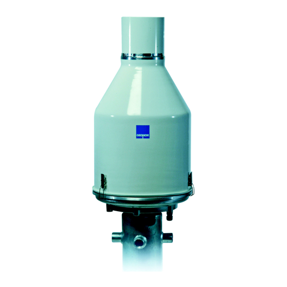
- Page 1 T-200B SERIES PRECIPITATION GAUGE MANUAL 600-mm, 1000-mm, 1500-mm & 3000-mm capacity gauges Rev: 11.10...
-
Page 2: Table Of Contents
TABLE OF CONTENTS 1. INTRODUCTION – PRECIPITATION GAUGE ....4 1.1. Principle of Operation ..............4 1.2. Why is it used ................4 1.3. Advantages ................4 2. INSTALLATION ............... 5 2.1. Foundation considerations ............5 2.2. Plan height of collection inlet............5 2.3. - Page 3 6. DRAWINGS / DIAGRAMS / FIGURES …………………………. 6.1. Gauge – vertical cross section – shows parts ......27 6.2. Connection of TH501 Interface & transient arrestor ....28 6.3. Concrete foundation block ............29 6.4. Gauge with 1-m pedestal and Alter windscreen ......30 7.
-
Page 4: Introduction - Precipitation Gauge
They use precision vibrating wire transducers (sensors) to weight and determine the amount of precipitation collected. The collection container in the T-200B Series gauge is suspended from three points, each supporting 1/3 of the weight. With this type of set-up there are options available to measure the precipitation with triple redundancy. -
Page 5: Installation
2. INSTALLATION IMPORTANT: A solid foundation and rigid pedestal are needed for proper gauge performance. We recommend using a GEONOR pedestal. 2.1. Foundation considerations in soil, on rock, or on a structure Regardless of whether the pedestal is installed in soil, on rock or on a structure, the pedestal must be rigid enough to prevent movements and vibrations due to wind, frost heave, loosening of soil, etc. -
Page 6: Pedestal Installation
IMPORTANT: A stable pedestal is required for accurate data. If there is movement of the gauge your data may be affect. 2.4.1. Pedestal details We recommend the T-200B gauge be mounted on a GEONOR pedestal. GEONOR provides galvanized steel pedestals in 1 m and any custom height. - Page 7 2.4.2. Installing pedestal Mount the reaction nut, lock washer and washer on anchor bolt approx 1” above the surface . *Do not let pedestal rest on concrete base. (see Fig 7.7) Using the level, adjust the 4 reaction nuts so they are level and add the lock-washers and washers.
-
Page 8: Precipitation Gauge Installation
2.5. Precipitation Gauge installation 2.5.1. Remove gauge cover To remove the cover, release the 3 clamps around the base and lift it straight up. NOTE: Press hook into locking lugs to keep them from catching on base. (See photo 2-1) (Photo 2-1) 2.5.3. - Page 9 2.5.5. Install transducer/s & support chains IMPORTANT: The Sensor has a setscrew on the side which helps protect it. The screw must be loosened or removed for the sensor to work. Using 1 sensor: Install it at the northern support point. Install support chains in the other 2 support points.
- Page 10 Connect S-hooks of sensors to chains and support dish through holes. Place level across support dish. By turning the black knurl nuts on the sensors and chains fine-tune the level of the support dish making sure it is as level as possible. 2.5.6.
-
Page 11: Electrical Hookup At Gauge
2.6.2. Connect wires from Transient Arrestor to Interface (TH501) The wires should be properly shielded and be suitable for the environment to which it will be exposed. Geonor can supply any length cable required. Pass cable through the base of the gauge and the strain-relief connector supplied. -
Page 12: Antifreeze - As Needed
2.7. Add antifreeze as needed When the gauge is operating below 0°C, an antifreeze blend must be added to keep collected precipitation in a liquid state. If the precipitation freezes the sublimation may occur and eventually the container may break. It is important to notice that the capacity of the collected precipitation is decreased when antifreeze is added. -
Page 13: Loosen Setscrew On Transducer
To prevent undesirable effects of wind turbulence around the gauge, a Wind Screen should be installed. The GEONOR pedestal has Wind Screen mounts on the pedestal. Using the Geonor Alter Wind Screen assures a proper installation at the specified, 13-mm height above the top of the gauge orifice. -
Page 14: Connect To Data Logger
2.12. Connect to data logger Use 22 AWG wire to connect the TH501 interface and the SDI12 interface to the data logger inside the enclosure. The Sensor is audible when power (9-16VDC) is supplied. Each transducer is slightly different but the approximate range is from 1000 Hz when empty to 3000 Hz with a full container. -
Page 15: Connect Data Logger Using Th501 Interface
2.13. Connect data logger using supplied TH501 Interface. 1. Connect the +/- from the precipitation gauge to A (+) and B (-) on the TH501 interface. 2. From the TH501, connect B to (-) or ground port and connect V (+) to signal port on data logger. -
Page 16: References
3. REFERENCES Bakkehøi, Steinar; Kjell Øien and E. J. Førland (1985) An Automatic Precipitation Gauge based on Vibrating-Wire Strain Gauges, Nordic Hydrology No. 16, pp. 193-202 Tunbridge, Lloyd and Kjell Øien (1988) The advantage of Vibrating Wire Instruments in Geomechanics, 2 Intl. -
Page 17: Mounting Alter Wind Windscreen
4. INSTRUCTIONS FOR ALTER WINDSCREEN INNER ALTER WINDSCREEN PARTS 1. Blades (qty 32) 2. Spacers (qty 24) 3. Ring segments (qty 4) 4. Ring segment connectors (qty 4) 5. Kee-Klamps for ring segments (qty 4) 6. Kee-Klamps, 90° pipe fitting (qty 4) 7. - Page 18 (Photo 3-1 – Single Alter windscreen) (Photo 3-2 – Double Alter windscreen) Rev: 11.10...
- Page 19 1. Mark 500-mm from the threaded end on the horizontal pipes for Inner Alter and mark 1000-mm for Outer Alter. Mount connectors for ring segment on vertical sections of pipe. Mark 817-mm below the connector by wrapping tape around the pipe several times. This marks the level of the Kee-Klamp.
- Page 20 3. Insert horizontal tubes into the threaded fittings on the pedestal. Tighten with pipe wrench. 4. Slide the Kee-Klamps on so the inside edge lines up with the 500-mm mark and 1000-mm mark if applicable. 5. Align the clamps vertically and tighten nut with Allen key supplied. Adjustments will to be made later.
- Page 21 6. Insert vertical pipes for Inner Alter in Kee-Klamp with connector for ring at top. The tape will rests on the Kee-Klamp. 7. Lay ring segments of inner Alter down and attach a ring connector to end of each segment. Slide the blades and spacers on in order shown below. Keep the channels of the blades facing away from the gauge Connect the segments to complete a full circle.
- Page 22 9. Install Kee-Klamps on top of vertical pipes. 10. Make adjustments. If using a double Alter windscreen configuration, it requires the installation of cement foundations for the 8 outer posts. A diagram and dimensions can be found on page 23. We suggest installing the pedestal first and use the horizontal sections with the Kee-Klamp to hold 4 of the vertical post in place while cement cures.
- Page 23 Rev: 11.10...
-
Page 24: Maintenance
5. MAINTENANCE 5.1. Tools needed • Screw driver, 4-mm blade • Hammer • Adjustable spanner (wrench) 0-27 mm • Container for disposal of anti-freeze mixture • Funnel • Measuring cylinder, 1 liter Supplied tools • Siphon • Level 5.2. Service interval Service the gauge when the container needs to be emptied. -
Page 25: Check Function Of Transducer
Any type of contact can contribute to error. When installing a new or recalibrated sensor, use the new values for A, B and f . These are given on the calibration sheet with the sensor. GEONOR model P-520M portable frequency counter. Rev: 11.10... - Page 26 6. DRAWINGS / DIAGRAMS / FIGURES 6.1. T-200B Gauge – vertical cross section – shows parts ..27 6.2. Transient Arrestor, TH501 Interface & SDI12 Interface ..28 6.3. Concrete foundation block ............29 6.4. Gauge with 1m pedestal and Alter Windscreen ....23 Rev: 11.10...
- Page 27 Rev: 11.10...
- Page 28 Figure 1. Transient Arrestor, TH501 Interface & SDI12 Interface. Rev: 11.10...
- Page 29 Rev: 11.10...
- Page 30 Rev: 11.10...
- Page 31 7. SAMPLE PROGRAM FOR CAMPBELL SCIENTIFIC CR1000 Note: On the CR1000 when PConfig is set to 0 this equals "High Frequency" On the CR1000X when PConfig is set to 0 this equals "Disabled" On the CR1000X when PConfig is set to 3 this equals "High Frequency with pull up" 'Declare Public Variables Public PTemp, batt_volt Public Freq1_hz As Float,Freq2_hz As Float,Freq3_hz As Float...
- Page 32 Scan (1,Min,0,0) 'SN 36510 1500-mm Sensor PulseCount (Freq1_hz,1,1,0,1,1.0,0) ‘On CR1000X set PConfig to 3 Precip1_cm=0.0294422*(Freq1_hz-1078.2)+0.0000162948*(Freq1_hz-1078.2)^2 Precip1_mm=Precip1_cm*10 Precip1_in=Precip1_cm*0.3937 'SN 33812 1500-mm Sensor PulseCount (Freq2_hz,1,2,0,1,1.0,0) ‘On CR1000X set PConfig to 3 Precip2_cm=0.0290427*(Freq2_hz-1089.4)+0.0000158857*(Freq2_hz-1089.4)^2 Precip2_mm=Precip2_cm*10 Precip2_in=Precip2_cm*0.3937 'SN 33112 1500-mm Sensor PulseCount (Freq3_hz,1,11,0,1,1.0,0) ‘On CR1000X set PConfig to 3 Precip3_cm=0.0291480*(Freq3_hz-1091.4)+0.00000161437*(Freq3_hz-1091.4)^2 Precip3_mm=Precip3_cm*10 Precip3_in=Precip3_cm*0.3937...
- Page 33 8. SAMPLE EVENT Rev: 11.10...
Need help?
Do you have a question about the T-200B Series and is the answer not in the manual?
Questions and answers