Table of Contents
Advertisement
Quick Links
Advertisement
Table of Contents

Related Manuals for Mueller Elektronic TRAIL-Control

Summary of Contents for Mueller Elektronic TRAIL-Control
- Page 1 Installation and Operating Instructions TRAIL-Control - Manufacturer - Release 03-2001 ______________________________________________________________________________ Müller Elektronik GmbH & Co. KG Franz-Kleine-Str. 18 33154 Salzkotten Datei: 302901-02_E(ME015488)_PDF.DOC 17510217-EN...
-
Page 2: Table Of Contents
Contents Overview .......................5 Security........................6 2.1. Disclaimer: ......................6 2.2. Safety precautions ....................6 Mounting Instructions - TRAIL-Control............7 3.1. Computer........................7 3.2. 12V Power Supply ....................7 3.3. Switching Box Implement..................7 3.4. Potentiometer (Poti) ....................8 3.4.1. Mounting of the Tractor Potentiometer..............8 3.4.1.1. Trailer Coupler .......................8 3.4.1.2. - Page 3 Hydraulic System Closed Centre .................29 8.4. Hydraulic System Closed Centre and "N" as Flow Through .......30 8.5. Hydraulic system Load sensing................31 8.6. Locking Screw for Valve ..................32 8.7. Lock valve ......................33 ______________________________________________________________________________ Copyright Müller-Elektronik GmbH & Co. KG TRAIL-Control 30290102 Manual Manufacturer Page 3...
- Page 4 ______________________________________________________________________________ Copyright Müller-Elektronik GmbH & Co. KG TRAIL-Control 30290102 Manual Manufacturer Page 4...
-
Page 5: Overview
Switching box Houses the sensor and actuator connections of the implement Socket for switching box Connection to TRAIL-Control Computer Lock sensor with magnet Sensor recognises active lock in case magnet is in position in front of it. Plug for hydraulic valve... -
Page 6: Security
Always watch for this symbol to point out important safety precautions. It means attention! Become alert! Your safety is involved. Always read this operators manual before using the equipment. ______________________________________________________________________________ Copyright Müller-Elektronik GmbH & Co. KG TRAIL-Control 30290102 Manual Manufacturer Page 6... -
Page 7: Mounting Instructions - Trail-Control
For old housing systems until ´93 article number 302915 is to be used. 3.2. 12V Power Supply The TRAIL-Control is being power supplied through the switching box of the implement. In case no socket is available, you can obtain a special battery cable with article number 312154 . -
Page 8: Potentiometer (Poti)
3.4. Potentiometer (Poti) 3.4.1. Mounting of the Tractor Potentiometer 3.4.1.1. Trailer Coupler ______________________________________________________________________________ Copyright Müller-Elektronik GmbH & Co. KG TRAIL-Control 30290102 Manual Manufacturer Page 8... -
Page 9: Hitch
Warning: If the 10 cm are undershot it can happen that the bar falls off during the drive Fix the mounting angle on the drawbar. This serves for the absorption of the angle transmitter when the machine is moved from the tractor. ______________________________________________________________________________ Copyright Müller-Elektronik GmbH & Co. KG TRAIL-Control 30290102 Manual Manufacturer Page 9... -
Page 10: Mounting Of Implement Potentiometer
Bend the bar so that it run parallel to the drawbar through the angle support. Fix the angle transmitter on the drawbar. The bar should run at least 2 cm through the angle support. ______________________________________________________________________________ Copyright Müller-Elektronik GmbH & Co. KG TRAIL-Control 30290102 Manual Manufacturer Page 10... -
Page 11: Wheel Steering
Bend the bar so that it run parallel to the axis through the angle support. Fix the angle transmitter on the axis. The bar should run at least 2 cm through the angle support. ______________________________________________________________________________ Copyright Müller-Elektronik GmbH & Co. KG TRAIL-Control 30290102 Manual Manufacturer Page 11... -
Page 12: Electrical Connection Of The Potentiometers
Some potentiometers are equipped with different cables with varying colours. See the following table before connecting the wires: Switching box Colour of the connector wire + 12V Brown Signal Green/Yellow Ground Blue ______________________________________________________________________________ Copyright Müller-Elektronik GmbH & Co. KG TRAIL-Control 30290102 Manual Manufacturer Page 12... -
Page 13: Potentiometer Check With Multi Meter
3.4.2.4. Potentiometer check with multi meter Both potentiometers can be examined with a multi meter. The voltage can be measured in the switching box at the connector of the potentiometers. The TRAIL-Control computer must be switched on. Attention! The hydraulics must be switched off to prevent erratic movement of the machine. -
Page 14: Lock Sensor
As long as the steering is locked, all lamps will be lit. When the start key is released the unit will be switched off again. Magnet mit Schraube Halter Verriegelungs-Sensor 15 - 25mm Verriegelungs-Bolzen ______________________________________________________________________________ Copyright Müller-Elektronik GmbH & Co. KG TRAIL-Control 30290102 Manual Manufacturer Page 14... -
Page 15: Hydraulic System
If it is necessary to change the working direction, only the hoses may be changed. The electrical connections must be always at the same place as described in the picture above. This is important because of the different current the coils work with. ______________________________________________________________________________ Copyright Müller-Elektronik GmbH & Co. KG TRAIL-Control 30290102 Manual Manufacturer Page 15... -
Page 16: Control Function Check
Before mounting the remote control cable of the tractor potentiometer the proper function of the TRAIL - Control should be checked. Please proceed as follows: > switch off hydraulic system. > switch on TRAIL-Control using the - key. > switch on automatic mode using the - key. - Page 17 Turning the manual control key to the left should move the implement to the left. If the implement does not respond in this manner, please start the check again. ______________________________________________________________________________ Copyright Müller-Elektronik GmbH & Co. KG TRAIL-Control 30290102 Manual Manufacturer Page 17...
-
Page 18: Operating Instructions
Pressing the key once more, the mode “automatic” is switched on again. Optional the key “centre position” can be pressed to switch to mode “centre position”. ______________________________________________________________________________ Copyright Müller-Elektronik GmbH & Co. KG TRAIL-Control 30290102 Manual Manufacturer Page 18... -
Page 19: Centre Position / Manual Key
(other than the tractor's). In addition, in calibration mode it is possible to fine-tune the controller with this key. Please note, that in normal working mode the turnkey should be in centre position. ______________________________________________________________________________ Copyright Müller-Elektronik GmbH & Co. KG TRAIL-Control 30290102 Manual Manufacturer Page 19... -
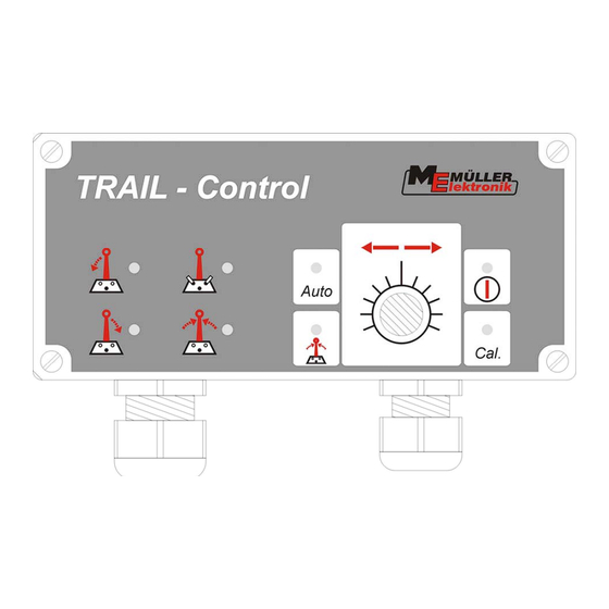
Page 20: The Display Devices
4.4. The Display Devices In addition to the control lamps in the keys the TRAIL-Control has 4 lamps to display certain modes of the device. 4.4.1. Control Left Lamp This control light burns when tractor is making a left turn and the controller is active. It turns out when the controlling process has been finished. -
Page 21: Basic Tuning
> Wait until control lamp centre position is on > press -key control lamp in -key turns off. > switch the unit off using -key ______________________________________________________________________________ Copyright Müller-Elektronik GmbH & Co. KG TRAIL-Control 30290102 Manual Manufacturer Page 21... -
Page 22: Adjust Manual Control Key
Loosen the screw underneath, remove the knob and put it on again in the right position. Screw on tight and replace the red cap. To check the new position, repeat the steps 2 to 6. Switch the Trail-Control off with the key. ______________________________________________________________________________ Copyright Müller-Elektronik GmbH & Co. KG... -
Page 23: Learning Final Stops
5.2. Learning Final Stops The mechanical final stop of the steering should be learned by the TRAIL-Control in order for the device to shut off properly. This helps avoiding overheating of the hydraulic system and rough polling of the final stops. Please proceed as follows. -
Page 24: Return To Basic Tuning
5.3. Return to basic tuning TRAIL-Control contains a basic tuning for your implement that is active when delivered to you. You can alter these data following the procedures above. In case you want to get back your original tuning please follow the instructions below. -
Page 25: Trouble Shooting
Carry out basic tuning Too much play between Reduce the play coupler and draw bar Wrong machine type selected Check the DIP-switches inside the TRAIL-Control unit. No regulation Final stops are learned wrong Learn final stops (chapter 5.2) If this does not help,... - Page 26 After switching on device all Memory write error Return device to manufacturer keys are on and the lamp and -lamp flash ______________________________________________________________________________ Copyright Müller-Elektronik GmbH & Co. KG TRAIL-Control 30290102 Manual Manufacturer Page 26...
-
Page 27: Appendix
This version must be used for tractors with standard (Open Centre) hydraulics. Also it can be used at tractors with Load Sensing hydraulics. In this case only the TRAIL-Control valve is connected to the tractor. Other functions like boom lift and lower are controlled with a separate valve on the tractor. -
Page 28: Hydraulic System Open Centre With "N" As Flow Through
This version must be used for tractors with standard (Open Centre) hydraulics. Also it can be used at tractors with Load Sensing hydraulics. In this case only the TRAIL-Control valve is connected to the tractor. Other functions like boom lift and lower are controlled with a separate valve block, which is connected to “N”. -
Page 29: Hydraulic System Closed Centre
Control valve is connected to the tractor. Other functions like boom lift and lower are controlled with a separate valve on the tractor. It is important that the locking screw in the connector “N” is mounted. ______________________________________________________________________________ Copyright Müller-Elektronik GmbH & Co. KG TRAIL-Control 30290102 Manual Manufacturer Page 29... -
Page 30: Hydraulic System Closed Centre And "N" As Flow Through
Hydraulic System Closed Centre and "N" as Flow Through This version must be used for tractors with Closed Centre hydraulics. In this case the TRAIL-Control valve is connected to the tractor. Other functions like boom lift and lower are controlled with a separate valve block, which is connected to “N”. -
Page 31: Hydraulic System Load Sensing
This version can be used for tractors with Load Sensing hydraulics. For this the whole system must be prepared for Load Sensing. Otherwise the Open Centre version can be used at a Load Sensing tractor (See chapters 8.1 and 8.2). ______________________________________________________________________________ Copyright Müller-Elektronik GmbH & Co. KG TRAIL-Control 30290102 Manual Manufacturer Page 31... -
Page 32: Locking Screw For Valve
This locking screw is to be mounted to the connector "N" (see drawing). If no flow through is selected, "N" is being sealed by a screw with a copper washer. locking srew ______________________________________________________________________________ Copyright Müller-Elektronik GmbH & Co. KG TRAIL-Control 30290102 Manual Manufacturer Page 32... -
Page 33: Lock Valve
Mounting is really easy and can be done supplementary. The lock valve only needs to be fitted between the cylinder and the proportional valve (see drawing). Lock valve Prop. valve ______________________________________________________________________________ Copyright Müller-Elektronik GmbH & Co. KG TRAIL-Control 30290102 Manual Manufacturer Page 33...
Need help?
Do you have a question about the TRAIL-Control and is the answer not in the manual?
Questions and answers