Table of Contents
Advertisement
Quick Links
Advertisement
Table of Contents

Summary of Contents for SoundForce MOD6
- Page 1 MOD6 USER MANUAL 8 October 2024 – V1.4 Nicolas Toussaint...
- Page 2 Thank you Thank you so much for purchasing this module! SoundForce is a small business and I am grateful for everybody that supports it. I hope this module will bring you some fun and that it will complement your other modules well. This was my first development using a screen UI, I definitely learnt a lot and I am happy to say a lot has improved since the original Dual LFO and Dual ADSR designs.
- Page 3 Dual LFO and Dual ADSR modules, with the goal of merging them together into a powerful dual-function next-level module. It is the first SoundForce product using a screen-based UI. A small but crisp colored screen was chosen. From the start, the goal was to avoid the dreaded menu-diving user experience.
-
Page 4: Table Of Contents
Table of Contents FRONT PANEL CONTROLS ..................5 ADSR Section ........................ 5 LFO Section ........................8 DIGITAL INs/OUTs VOLTAGE RANGE ..............12 PARAMETRIC CV INPUTS AND OUTPUTS VOLTAGE RANGE ........12 HOW CV MODULATION IS APPLIED ................13 ATTENUVERTER MENUS AND CV 3/5 DESTINATION MENUS ........13 ATTENUVERTER MENUS ..................... -
Page 5: Front Panel Controls
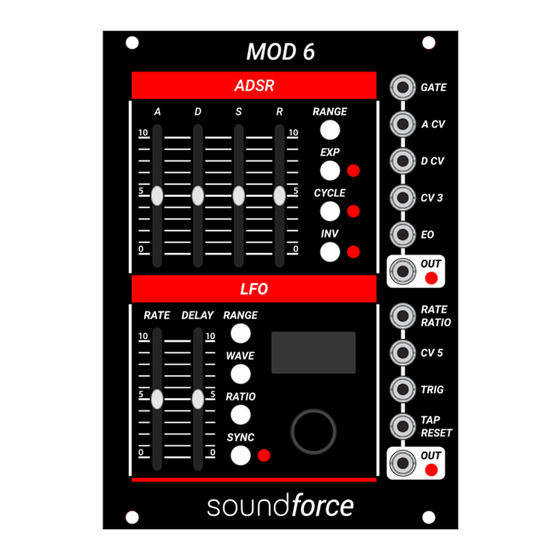
1. FRONT PANEL CONTROLS A. ADSR S ECTION A slider: This slide pot sets the time length of the envelope attack stage. The actual attack time will depend on the slider position, ADSR range selected and possible incoming CV on the A CV jack. - Page 6 S slider: This slide pot sets the level of the envelope sustain stage between 0 and 100%. The actual sustain level voltage will depend on the sustain slider position, the ADSR DAC output voltage range and incoming CV on the CV3 jack (if assigned to sustain). R slider: This slide pot sets the time length of the envelope release stage.
- Page 7 OUT jack: ADSR output signal jack. RANGE switch: The RANGE switch cycles through the 4 different time ranges of the ADSR: SHORT, MEDIUM, LONG and USER. ATTACK DECAY RELEASE SHORT From 200us to 1s From 500us to 1s From 500us to 2s MEDIUM From 1ms to 3s From 2ms to 12s...
-
Page 8: Lfo Section
B. LFO S ECTION RATE slider: This slide pot sets the rate of the LFO. It sets the LFO frequency either in Hz when the oscillator is free-running (SYNC is off) or as a divider/multiplier ratio of the base TAP input signal frequency when the SYNC is ON. - Page 9 DELAY slider: This slide pot sets the delay time of the LFO. The actual delay time will depend on the slider position and incoming CV on the CV 5 jack (when assigned to DELAY). The DELAY phase starts at a rising-edge on the TRIG jack. Trigger length has no impact on the LFO DELAY. The LFO signal can hold its center value or fade-in during the delay phase, see LFO options.
- Page 10 CV5 jack: CV5 control voltage input. Can be assigned to modulate either the delay time, the waveform selection or the LFO output level (as a digital VCA). When unused, set it to INACTIVE. TRIG jack: The TRIG input is used to start the delay phase of the LFO. The DELAY phase starts at a rising-edge on the TRIG jack.
- Page 11 WAVE switch: The wave switch displays the waveform selection menu. Turn the encoder to change the selected waveform. When CV 5 is NOT assigned to WAVE, the actual LFO waveform is the one currently displayed in the waveform selection menu. When CV 5 is assigned to WAVE, an additional OFF/ON selection is shown.
-
Page 12: Digital Ins/Outs Voltage Range
DIGITAL IN /OUT VOLTAGE RANGE The inputs (GATE, TRIG, TAP/RESET) will register a rising and falling edge when the signal passes the threshold of 0.7V. Signals from -12V to +12V can be tolerated by the module. Ideally unipolar signals of 0 to 5V, or 0 to 10V are used. The EO digital output signal has a range of 0V to 5V. -
Page 13: How Cv Modulation Is Applied
HOW CV MODULATION IS APPLIED Based on the CV input voltage range setting and the possible attenuvertion ratio, an internal CV modulation is calculated. Let's take an example with the A CV input to modulate the attack time. By default, the A CV range is -5V to +5V and the attenuvertion ratio is 100%. Connecting a 10Vpp bipolar sine signal to the A CV jack will result in an internal CV modulation of 100% for the attack time. -
Page 14: Cv3 Destinations
The ratio can be set between +100% and -100%. Negative values under 0% will invert the CV signal and attenuate. For CV 3 and CV 5, a destination setting is also available. To switch between attenuvertation ratio and destination control, press down the encoder. If CV 3/CV 5 are not used, set the destination to INACTIVE to avoid any unwanted offsets. -
Page 15: Adsr Options
ADSR OPTIONS To enter the ADSR options menu, press down the 4 ADSR switches (RANGE + EXP + CYCLE + INV) at the same time. By turning the encoder, you can scroll between the different options. Some options can be toggled on and off by simply pressing down on the encoder. Other options have more than 1 setting, you can start editing the settings by pressing down on the encoder to enter edit mode and press it down again to exit edit mode. - Page 16 INVERSION AROUND: Press down the encoder to toggle between ITSELF and 0V axis. The ITSELF option inverts the ADSR signal as a mirror around the middle of the ADSR DAC voltage range. While the 0V axis option inverts the ADSR signal around the 0V axis thus also inverted the sign of the voltage.
-
Page 17: Lfo Options
CV 3 RANGE: CV 3 input voltage range. Press down the encoder to start to edit the range min voltage and turn the encoder to change the value. Press again to edit the range max CV and turn the encoder to change the value. Press again the encoder to exit edit mode. DAC RANGE: ADSR output signal voltage range. - Page 18 WAVE CV MORPH: Press down the encoder to toggle between ON and OFF. When this option is OFF, CV 5 (when assigned to WAVE) will switch without transitions between the ON-selected waveforms in the WAVE menu. When this option is ON, the different ON-selected waveforms will gradually morph into each other based on the incoming CV 5 voltage.
-
Page 19: Lfo Waveform Cv Control
LFO WAVEFORM CV CONTROL Using CV 5 it is possible to CV control the waveform selection of the LFO. First, long press the LFO WAVE switch to access the CV 5 ATT menu. Press down the encoder to focus on DEST, and turn encoder to choose WAVE as CV 5 destination. -
Page 20: Calibration Data Reset
10. CALIBRATION DATA RESET NEVER RESET CALIBRATION WITHOUT GOOD REASONS! YOU NEED A PRECISE MULTIMETER TO CALIBRATE THE MODULE ACCURATELY. If for some reason, you need to reset the calibration, a hidden feature is available. Please don’t reset the calibration without consulting me in advance. You cannot use the module without recalibrating first. -
Page 21: Firmware Updates
In the LFO options menu, you can consult the currently running firmware versions. When available, Firmware updates will be posted on the SoundForce module update page. The BOOT switch on MOD 6 is located on the bottom of the PCB, it is the most left switch on the row of the 3 small metal switches.
Need help?
Do you have a question about the MOD6 and is the answer not in the manual?
Questions and answers