Advertisement
Advertisement
Table of Contents

Related Manuals for HAVKON INSTRUMENTS CPX.139

Summary of Contents for HAVKON INSTRUMENTS CPX.139
- Page 1 Air Handling Control Device CPX.139 User Manual HVAC-R Control Device...
- Page 2 CPX.139 Ahu air handling unit controller. The device must be used in accordance with the instructions. There In order to prevent electric shocks and similar accidents,...
- Page 3 1. ROOM PANEL 1.1. HCP Series Room Panel 3.1” Graphic Display Aspirator, Fan Speed Control Auto/Manual Operation Heating/Cooling/Fan Modes Selectable Language Option (Turkish/English) Built-in Room Temperature Sensor User Friendly Design Minimum and Maximum Set Temperature Limit Weekly program Doc: 24-08-22, v1.0, www.havkon.com...
- Page 4 Fresh Air Temperature Sensor Humidity Sensor CO2 Application Pressure Control Modbus RTU Weekly Schedule Functions CPX.139 Relay Output Digital Inputs Fan Fault Analog Output Safety Thermostat Boost Mod Analog Input Air Flow Information ...
-
Page 5: Technical Dimensions
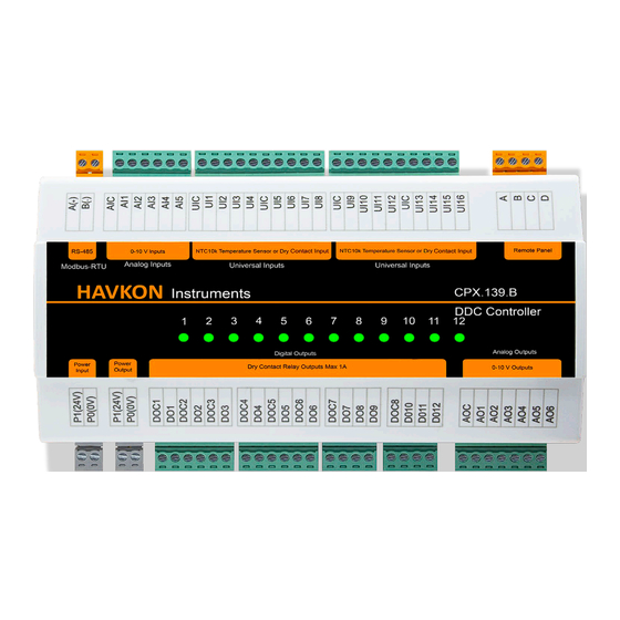
3. Technical Dimensions: Doc: 24-08-22, v1.0, www.havkon.com... - Page 6 4. Giriş ve Çıkışlar Modbus RTU Analog Inputs Universal Inputs Panel Analog Outputs Dijital Outputs 24 V AC/DC Power Output 24 V AC/DC Power Input Doc: 24-08-22, v1.0, www.havkon.com...
-
Page 7: Technicial Specifications
5. TECHNICIAL SPECIFICATIONS Supply 24 V AC/DC Electrical Data Power consumption Max 5VA Connection 1,5mm² klemens Relay Output 12 Piece (Max 2A) Analog Output 6 Piece (0 – 10 V) Functions Analog Input 5 Piece (0-10V) Universal Input 16 Piece (NTC10k or Dry Contact) Mounting Type Rail Mounting Physical Data... -
Page 8: Functional Features
6. Functional Features: Open/close control facility from BYS system (Dry contact) Control with Channel Type Sensor Fresh Air Damper Control Bypass Air Damper Control External Sensor Connection (Blowing Temperature, Supply Air Temperature, Fresh Air Temperature, Heating Coil Temperature) ... - Page 9 7. ROOM PANEL USE On/Off Button Manages the ON/OFF functions of the device. Mode/OK Button Selects the operating mode of the device (Automatic Heating/Automatic Fan/Manual). Up Button In manual mode, it increases the fan stage. In automatic mode, the Set Temperature increases. Down Button Decreases the fan step in manual mode and Set Temperature in automatic mode.
- Page 10 How to Set Date and Time? When the device is on, press the SETUP button on the panel for 2 seconds. Select Date Time Set with the Down button and press the Mode/OK button. Select day, month and year setting with Up or Down button and proceed using Mode/OK button.
- Page 11 How to Change Set Temperature? If the device is in manual or automatic heating mode when the device is on, the set temperature is set to flash by pressing the MODE/OK button and the set temperature is adjusted with the UP DOWN buttons.
- Page 12 How to Reset the Fault? If the fault code flashes in the upper corner of the screen and the fault is fixed, the fault is reset by pressing the SETUP button and UP button at the same time while the screen is on. How to Reset Time Based Filter Dirty? (Optional) ...
- Page 13 How to Change Device Language? When the device is on, press the SETUP button for 2 seconds to enter the settings menu. Language selection is made with the DOWN button. It is entered with the MODE/OK button. With the UP button, the desired language is reached and the MODE/OK button is pressed and saved.
- Page 14 How to Adjust Light Intensity? While the device is on, press the SETUP button for 2 seconds. In the settings menu that appears, the • Light Intensity is selected with the DOWN button and the MODE/OK button is pressed. With the UP and DOWN buttons, the screen brightness is adjusted to the desired level and the MODE/OK button is pressed.
- Page 15 How to Adjust Contrast? The SETUP button is pressed for 2 seconds while the device is in an open position. From the settings menu, the DOWN button flashes the Contrast Setting and the MODE/OK button is logged in. Contrast adjustment is made with the UP and DOWN button on the display.
-
Page 16: Using The Service Menu
8. USING THE SERVICE MENU To enter the user service menu: When the device is powered, press the UP and DOWN buttons on the panel at the same time. On the screen that appears, enter the service password using the UP and DOWN buttons and press the MODE/OK button. - Page 17 Note1: Service menu password is 58. Note2: Other Modbus parameters Data bit8, Data parity bit none (N), Stop bit 1 cannot be changed. Note3: All Modbus Parameters are holding register. Note4: All Modbus parameters are Signed Integer 16. Attention The changes to be made in the Service Setting Menu must be made by the relevant technical personnel.
- Page 18 CPX.139 MODBUS REGISTER LIST V1.0 Parametre Name MIN/MAX Value Register General Device Control Values Device Open / Close 40001 0…1 0:OFF / 1:ON Variable Device Set 40002 0...999 280 value means 28 ºc Temperature 0: Fan Mode 1: Heating Man Device Air 2: Man.
- Page 19 Heat Exchanger 40014 -400...999 Temperature Value Instant Device Input Status Indicator Registers 0. Bit ==> Bms Input 1. Bit ==> Boost Input 2. Bit ==> Aspirator Fan Air Flow Information 3. Bit ==> Fan Fan Air Flow Information 4. Bit ==> Filter 1 Dirty Info 5.
- Page 20 It works according to Analog Input Calibration 40041 High Pressure Value 0….30.000 values. Proportional Damper Registers 40042 Mix Damper Mode Mixture Damper 40043 Manual Mode Fresh 0…1000 550 is Selected for 55% Fresh Air Air Value Digital Output Instantaneous State Registers 0==>...
- Page 21 Proportional Cooling 40068 0...1000 Valve Output Value Proportional 40069 Heating/Cooling Valve 0...1000 Output Value Proportional ByPass 40070 0...1000 Damper Output Value Mixing Damper Output 40071 0...1000 Value 40072 VRF Output Value 0...1000 Weekly Program Time Setting Parameter Registers Sunday Start Time: 40073 0...2359 Minutes...
- Page 22 Menu Setting Parameters 40096 Alarm Value 0…65.535 40097 Warning Value 0…65.535 Menu Setting Parameters 40098 Fan Mode Show Menu 0...1 Manual Heating Show 40099 0...1 Menu Manual Cooling Show 40100 0...1 When the device is on, the screens to be Menu displayed in the desired screens in the operation Auto Heating Show...
- Page 23 6:57600Bps Display Value Display Registers 0: Don't show 1:Show Outside Temperature Show Temperature 40114 0...3 2:Display Temperature Value 3: Display Outdoor and Discharge Temperature Simultaneously 0: Don't show 1:CO2 40115 114 Show Analog Input 0…4 2:AirQuality 3: Humidity 4: Show CO2 + Humidity Simultaneously Filter Counter Timer This counter increases on an hourly basis as 40116...
-
Page 24: Fault List
Fault List Değer Binary Açıklama Binary Explanation 0000.0000.0000.0001 Aspirator Fan Failure 0000.0000.0000.0010 Vantilator Fan Failure 0000.0000.0000.0100 Electrial Heater Failure 0000.0000.0000.1000 Aspirator Air Flow Error 0000.0000.0001.0000 Vantilatör Air Flow Error 0000.0000.0010.0000 Compressor Failure 0000.0000.0100.0000 Low Pressure 0000.0000.1000.0000 High Pressure 0000.0001.0000.0000 Fire Alarm 0000.0010.0000.0000 Phase Failure 1024 0000.0100.0000.0000... - Page 25 9. Klima Santrali Bağlantı Şeması Doc: 24-08-22, v1.0, www.havkon.com...
Need help?
Do you have a question about the CPX.139 and is the answer not in the manual?
Questions and answers