Table of Contents
Advertisement
Quick Links
Advertisement
Table of Contents

Summary of Contents for Martin Yale Industries PostMark ENVEJET 1170
- Page 1 ENVELOPE PRINTER User Manual Serial #:...
-
Page 3: Need Support
**Please review below notes prior to operation of the machine** General Warranty: 1-year parts, 90-days labor for machine. Printer is 4L per color per printbar or 300mL per die per color, whichever comes first (can be checked on the “Printbar” tab of the Windows Interface). Postmark printers are to be used exclusively with official HP consumables, including but not limited to ink cartridges and service sleds. -
Page 4: Table Of Contents
TABLE OF CONTENTS 1.0 ABOUT THE 1170 ENVEJET ..........................4 1.1 SAFETY & REQUIREMENTS .......................... 4 1.1.1 OPERATIONAL REQUIREMENTS ..........................4 1.1.2 ENVIRONMENTAL REQUIREMENTS ......................... 4 1.1.3 SETUP REQUIREMENTS ............................4 1.1.4 DURING USE ................................5 1.1.5 AFTER USE .................................. 5 1.1.6 SHIPPING CONSIDERATIONS ........................... - Page 5 3.2.3 ARTWORK SIZE ................................ 30 3.2.4 PRINT RESOLUTION ..............................31 3.2.5 FILE SIZE ................................... 31 3.2.6 SPOT COLORS ................................31 3.3 SOFTWARE - 1170 WINDOWS INTERFACE ....................32 3.3.1 USES ..................................33 3.3.2 HOME TAB ................................. 33 3.3.3 PRINTBAR TAB ................................33 3.3.4 SETTINGS TAB ................................
-
Page 6: About The 1170 Envejet
1.0 ABOUT THE 1170 ENVEJET 1.1 SAFETY & REQUIREMENTS Please read the owner’s manual. Follow instructions carefully. 1.1.1 OPERATIONAL REQUIREMENTS IMPORTANT: Failure to act within the policies and procedures found within this document may cause machine damage. Any damage found to be caused by abuse, neglect, or misuse due to noncompliance with these instructions may void the machine’s warranty. -
Page 7: During Use
Worktable 233 lbs. / 106 kg Conveyor 45 lbs. / 20.5 kg Printer 62 lbs. / 28 kg Delivery Conveyor 21 lbs. / 9.5 kg 1.1.4 DURING USE Moving Parts Keep fingers and hands away from all rotating parts. Keep cords clear of moving parts. -
Page 8: Specifications
1.2 SPECIFICATIONS HP FI-1000 (HP PageWide technology TIJ4 printer, replaceable as part of Printer BnB) Print Res (DPI) 1200 x 1200 and 600 x 1200 (per color) Print Speed (1200 x 1200 dpi) 18 in/sec, 98 ft/min (457 mm/sec, 30 m/min) Print Width 11.7"... -
Page 9: Component Identification
● Extra AAA Batteries (2) (Keyboard – comes with some but may need to be replaced later) ● (Mouse – comes with one but may need to be replaced later) Extra AA Battery (1) 1.4 COMPONENT IDENTIFICATION 1.4.1 MACHINE A. Transport Conveyor D. -
Page 10: Understanding Inkjet Terminology
1.4.2 UNDERSTANDING INKJET TERMINOLOGY Single Pass Inkjet Single pass inkjet means that the printer stays fixed in position and ink is ejected directly on the substrate as the media passes under the printer. This means that the maximum print width is determined by the size of the printer. For the 1170 printer that is 11.7”... -
Page 11: Replaceable Parts
• M-S045765 Ethernet: from printer to computer • M-S0E1329 Power supply cord: from main conveyor to outlet or power strip • M-S0E0974 Power supply cord from printer to main conveyor • M-S028131 6-pin Connection Cable: from exit conveyor to Motherboard PCB •... - Page 12 Other Wearable Parts PM-1170006 M4 x 25mm FF Standoff Printer PM-1170020 M3 x 22mm FF Standoff Printer PM-1170029 M4 x 16mm MF Standoff Printer PM-1170030 M4 x 8mm MF Standoff Printer PM-1170033 M4 x 25mm MF Standoff Printer PM-1170035 M4 x 60mm MF Standoff Printer PM-1170050 8mm x 12mm Round Spacer...
-
Page 13: Control Panel
1.5 CONTROL PANEL (Controls listed below in order of photo from left to right) 1.5.1 E-STOP Pressed Stops all 24 VDC power to the conveyor, delivery conveyor, and connected peripherals Red LED will illuminate when depressed Turn Clockwise Returns 24 VDC power to system after Reset Button is pressed to Reset 1.5.2 RESET BUTTON Pressed... -
Page 14: Setting Up
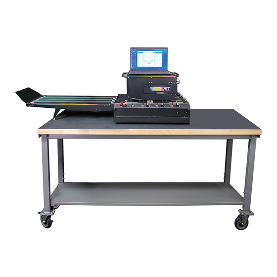
2.0 SETTING UP 2.1 EQUIPMENT SETUP 2.1.1 CONFIGURATION Below is a standard setup with the system feeding from right to left. Note that the laptop is set on top of the printer. Bleed Channel or No Bleed Channel For non-bleed applications, the printer can be repositioned by sliding the printer toward the feed-side to print over the belt. -
Page 15: Conveyor & Delivery Conveyor
2.1.2 CONVEYOR & DELIVERY CONVEYOR Attaching the Delivery Conveyor Next place the delivery conveyor on the exit side of the transport conveyor. There are 2 slots on the entry side of the delivery conveyor that correspond to two thumbscrews on the exit side of the conveyor. These may need to be loosened before attaching. -
Page 16: Mounting The Printer
Retainer Clips The orange retainer clips are shown on the right. These are used to prevent movement during shipping and must be removed for operation. Remove them and set them aside. Once the clips are removed, reinstall the service sled panel and replace the spring-steel envelope guides. Do not throw away service sled inserts. -
Page 18: Setting Up The Printer
2.2 SETTING UP THE PRINTER 2.2.1 PRINTER CONNECTIONS Printer Power Cable Non-Operator Side Ethernet Connection (See section 2.4.1)* Right Operator Side (to PC or Switch) USB-B Connection Right Operator Side USB-A Connection** (for log files) Right Operator Side (to PC or Switch) TOF Sensor Cable (See section 2.2.2) Right Operator Side (to TOF Sensor) Encoder Cable... -
Page 19: Tof Sensor
Connect the Encoder Cable first. Note recommended cable routing in image above. Once all connections are made, power on the printer (left side) and conveyor (non-operator side). Note: LED power button light color does not indicate status. Occasionally, printers with different LED colors will be shipped depending on what is available. -
Page 20: Loading Ink Cartridges
See Section 2.4 "Network Setup” for continued instructions. Dongle Insert the Xitron dongle license key into one of the open USB ports. 2.3 LOADING INK CARTRIDGES The 1170 line of printers use 4 ink tank cartridges that provide ink to the 1170 printer. These cartridges provide the BNB with ink and are smart cartridges that have a chip to keep track of ink usage. -
Page 21: Network Setup
2.4 NETWORK SETUP (Technician Use Only) 2.4.1 ETHERNET CONNECTIONS Configuration 1: Local Shared Network One configuration option is to connect the printer to the local network. To do so, connect an ethernet cable from the network router to a switch. From the switch, connect two additional ethernet cables: one to the computer, and one to the printer. - Page 22 Determine the IP Address 1. Go to the File Explore > Network > Printers 2. Find one that says HP FI-1000 (Fixed Imager Printer). 3. Double-click the HP FI-1000 printer to open the printer’s Embedded Web Server in the browser Location 1: Windows Interface Simply add the IP address to the “Settings”...
-
Page 23: Setting A Static Ip Address
Check: Navigator Client This does not always need to be done, but it should be checked as it can create issues later if not done. 1. Select the DFE folder on the right side of the client. Click the “edit” pencil icon. 2.4.4 SETTING A STATIC IP ADDRESS NOTE: This does not always need to be done. - Page 24 If the printer does not show up on the network, check that the orange light on the printer is illuminated and an Ethernet cable is connected to the entry side of the printer. Also, ensure that the computer’s network settings have network discovery turned on.
- Page 25 Browser: Google Chrome Browser: Windows Edge A warning saying “Your connection is not private” may A warning saying this site is not secure may come up - come up - this is normal. Click the “Advanced” button this is normal. Click the details button followed by the button that says “Go on to the web page”: followed by the button that says “proceed to [IP Address]”:...
- Page 26 The following settings screen should now be visible: A manual IP address can now be set along with subnet Mask and Default gateway. The “Suggest a Manual IP Address” button can be used to take settings currently used by the printer - this is useful to make sure that the subnet mask and default gateway are compatible with the network.
-
Page 27: Disabling Energy Settings
2.4.5 DISABLING ENERGY SETTINGS The printer can go offline occasionally due to default power save modes. To prevent network disconnection, disabled the power save settings for the network device. 1. Navigate to “Device Manager,” find the appropriate network adapter driver: Intel(R) or Realtek, then right click and select “Properties.”... -
Page 28: Calibrating The Printer
7. Navigate to the “Power Management” tab 8. Un-check “Allow the computer to turn off this device to save power” 9. Click “OK” to apply changes. 2.5 CALIBRATING THE PRINTER Once the hardware and network set up are complete, the printer needs to be recalibrated. The calibration performed at the factory is for functionality testing only. -
Page 29: Set The Top-Of-Form (Tof) Distance
2.5.1 SET THE TOP-OF-FORM (TOF) DISTANCE Before beginning any prints, adjust the TOF distance in the 1170 Windows Interface. This setting is the first slider adjustment located in the Admin Console. This should be set to 13.15 in / 334mm for the 1170 EnveJet. To test this, print a Test Sheet from the Home tab so that the small lines at the top of the print are on the edge of the sheet. -
Page 30: Adjusting Height
2.5.3 ADJUSTING HEIGHT Check that the printer is high enough off the belt. An indicator that the printer is too high is “clouding” or blurring of the die sections, or consistent gaps between all dies. 2.5.4 ADJUSTING ZONE OVERLAP This can be adjusted under “Calibrate” on the “Settings” tab. After printing a test-print, assess the lines between each of the dies and determine whether they are overlapping (darker) or gapping (white). -
Page 31: Adjusting Drop Density
TOF = Top of Form This can be adjusted under “Calibrate” on the “Settings” tab. The adjustment of the TOF offset is measured in 1/1200” so adjustments in increments of 1 are hardly visible to the human eye. It is recommended to start with increments of 5 or 10 for course adjustment, then smaller increments as needed. -
Page 32: Software & Operation
3.0 SOFTWARE & OPERATION 3.1 QUICK JOB SETUP In-depth steps can be found following this section, but the standard job setup process for #10 envelopes is as follows: 3.1.1 JOB PRINTING Upload a job and make any necessary adjustments such as rotation, scaling, media size, etc. Select the desired resolution and paper profile, set the quantity to one (for test print), and click “Print.”... -
Page 33: Print Resolution
Similarly, when printing an image using a Media Size that is larger than the artwork file, a gray box will be displayed around the artwork. This gray space is beneficial because it gives enough clearance to reposition the artwork without cropping it. Any part of the artwork positioned outside of the gray space will be cropped. However, the gray space will have a similar effect on print speed as uncropped whitespace in the artwork. -
Page 34: Software - 1170 Windows Interface
1. Select Color 2. Open Swatch Options Select the element with desired color. Double-click the highlighted swatch in the Swatches Panel. 3. Color Type 4. Verify Spot Color Change the Color Type from “Process Color” to Verify the swatch is a spot color by looking “Spot Color.”... -
Page 35: Uses
3.3.1 USES The 1170 EnveJet Printer includes and requires the 1170 Windows Interface. This is used for printer settings and maintenance. The interface consists of 3 sections: Home, Printbar, and Settings. 3.3.2 HOME TAB This tab shows the printer's status and any error codes for troubleshooting. -
Page 36: Settings Tab
3.3.4 SETTINGS TAB Under this tab, there will be a lock on the right side of the window. Click this icon to unlock additional adjustment settings. This section is where most of the adjustments will be made. NOTE: On older versions of this interface, the unlock button is the “O”... -
Page 37: Interface & Controls
to support a host of inkjet drive electronics and printers from many manufacturers. Using a scalable RIP farm system allows for any printing speed to be matched. Navigator DFE comes with the 1170 EnveJet Printer, and is the best, most versatile print software to use with the 1170 EnveJet. -
Page 38: Printing A Job
1. Add Job button Locate the add job button on the web interface. Select the + button. Navigate to the file in the pop-up window. Select the file, then select the OPEN button. 2. Drag and Drop Simply drag a PDF right over the "Add Job" button. When the icon of the PDF says "Copy,"... - Page 39 Quick Edits & Full Job Editor After the file is uploaded, the Quick Edits screen is opened. Various adjustments such as rotations, print range, collation, etc. are available on this screen. By selecting the Full Job Editor at the top right, additional adjustments become available such as changing the Paper Profile, Overall Color Changes and Spot Color Adjustments...
-
Page 40: Rest Control
3.4.5 REST CONTROL REST Interface Options In the Navigator DFE, under settings, there is an FI- 1000 tab, where you can adjust your level of REST control. There are 3 options described below. REST Interface: Full Control (Recommended for Variable Data and Static Data) This will allow the MJS, PPS, and TOF settings to be adjusted in the DFE settings, and NOT the Windows Interface. - Page 41 PPS Adjustments This is the distance that the Printbar will come down to the paper. The recommended default for this is 5120 but it can be adjusted to allow for print clarity depending on the substrate. TOF Adjustments This is the distance from the Top of Form (TOF) sensor to the printbar to allow proper timing.
-
Page 42: Adjusting Spot Colors In Xitron Navigator Dfe
3.4.7 ADJUSTING SPOT COLORS IN XITRON NAVIGATOR DFE NOTE: For steps on how to set a spot color before uploading the file to Navigator DFE, see section 3.4.7 “Setting Spot Colors.” Swatchbook Icon After setting a Spot Color, when it is uploaded in Xitron Navigator DFE, a “swatchbook”... -
Page 43: Icc Color Profiles
look “dotty” and of poor quality when viewed closely. To prevent this from happening, the FI-1000 technology uses a formula that measures minimum brightness, or in other words, drop density. For example, this means that for lighter, brighter colors, particularly bright orange and lime green, it will lean magenta for orange, cyan for lime green, or a muted version of either. -
Page 44: Software - Variegator Add-On
3.5 SOFTWARE - VARIEGATOR ADD-ON 3.5.1 WHEN TO USE The Xitron Variegator software is an add-on that can be purchased for producing PDFs with variable data. While the Xitron Navigator DFE that comes standard with the 1170 EnveJet is capable of printing multi-page PDFs with variable data, additional software is required to produce this printable PDF. -
Page 45: Print Adjustments
3.6 PRINT ADJUSTMENTS There are a variety of ways to adjust and improve the quality of the print. After the first print, follow the steps below for the best possible print. 3.6.1 HEIGHT ADJUSTMENT (PRINT CLARITY) First, adjust the height of the printer. There are four thumb screws on the machine that turn clockwise for raising and counterclockwise for lowering the printer. -
Page 46: Advanced Operations & Adjustments
3.7 ADVANCED OPERATIONS & ADJUSTMENTS NOTE: The following operations should only be performed by a technician or someone who understands, in-depth, the workings of the printer. 3.7.1 WORKFLOWS Creating a Workflow To create a new workflow, duplicate the original “DFE” workflow and click the pencil icon. -
Page 47: Reinstalling Xitron Navigator
Finally, under “Render Action” set the paper profile, calibration, and resolution. Note there are 3 areas this needs to be done. Paper 300 should correspond with Production, and Paper 600 should correspond with High Resolution. Make sure that “device” is set to “FI-1000.” Switching Workflows In the Navigator Client, the first workflow in the alphabetical list will always be the default used when... - Page 48 Uninstalling Xitron First, stop the Service Location Protocol in “Services.” This can be found by searching “Services” in the Windows Start Menu. Next, go to the Windows Start Menu and scroll down to the folder titled “Navigator.” In the dropdown, find “Uninstall Navigator.”...
-
Page 49: Updating The Firmware
If you would like to keep your workflows, jobs, and others you will need to access the most recently dated archive folder (C:Navigator\Navigator\ArchiveDBs) then copy the files and replace into the new version at the following location: C:Navigator\Navigator. Launch, Login, and Links You may need to log back into the Client and the Server after the first launch. - Page 50 Solutions Either print a different orientation so that the line is consistent after decapping those nozzles or add “spit lines” either before or after the print to allow all the nozzles used to decap at the same time. Spit lines can be added using the settings in the Navigator DFE.
-
Page 51: Troubleshooting
4.0 TROUBLESHOOTING The 1170 EnveJet is a complex and delicate machine. For more detailed troubleshooting and instructions, visit support.postmark-usa.com and sign into the Knowledge Base. Only the most common issues are described below. 4.1 PRINT APPEARANCE Problem: Single streak through print. (NOT a clear gap at even increments, which would be a calibration or height adjustment.) Solution: This is tricky because it could be a variety of things. -
Page 52: Software Issues
Problem: Print not hitting the page. Solution: Adjust the TOF (Top of Form) Sensor Distance (coarse adjust) and Leading Edge Adjustment (fine adjust). This can be found in the Windows Interface under Admin Console of the Settings tab. The coarse adjustment should typically be set to 15.5” then adjust both fine and coarse accordingly until the print is correct. -
Page 53: Hardware Issues
NOTE: You should not need to adjust past 1mm. Doing so can put too much distance between the printbar and the ski, resulting in fuzzy prints regardless of printer height. “Mech PPS out of Range” Problem: Solution: This means that the printer is too low to the conveyor. Raise just slightly using the screws on the 4 corners of the printer, making sure to keep it level. -
Page 54: Care & Maintenance
5.0 CARE & MAINTENANCE 5.1 PRINTHEAD & CONVEYOR 5.1.1 PRIME THE NOZZLES REGULARLY Print full sheets at least once a week to keep nozzles moist. This will help prevent the nozzles from drying out. For best results, it is recommended to print a full 8.5”x11” sheet of each: Cyan, Yellow, Magenta, and Black. This ensures that all colors of all nozzles are primed. -
Page 55: Replacing Service Sled
Ejecting the Service Sled Once the panel has been opened go to the Admin Console on the Windows interface and select “Eject Service Sled.” This will move the sled closer to the opening where it can be removed. Once it is removed, set it aside or discard. -
Page 56: Common Error Codes
6.0 COMMON ERROR CODES For a full list of error codes for the Windows Interface, go to the “Error Codes” page in the 1170 Knowledge Base at support.postmark-usa.com. NOTE: For errors relating to ink cartridges, refer to the following (X is the pertaining error codes): XX.00.XX Black Ink Cartridge XX.01.XX... - Page 57 Turn the printer off, and then back on. Allow the printer to perform the start-up printhead maintenance. Warning 61.66.y0 A printhead nozzle health recovery routine was initiated and completed successfully. 61.66.10 A user-initiated Pen Cleaning routine completed successfully. 61.66.20 An automatic Extended Cleaning routine completed successfully. 61.66.30 A user-initiated Extended Cleaning routine completed successfully.
- Page 58 Error 61.C5.25 The printhead error was detected during the printhead wiper replacement procedure. Press Clear Error. The printer should auto–recover from this error. If the auto–recover fails, turn the printer off, then on. Error 61.C5.26 The printhead error was detected during the printhead wiper replacement procedure. Run the Sled Handler sequence If the error persists, replace the printhead wiper kit (4CC92A) Error 61.C5.E0...
- Page 59 See “Error 62.0x.01” for “x” die number codes. List of error codes: 62.0x.02 62.0x.03 62.0x.04 62.0x.05 62.0x.06 62.0x.07 62.0x.08 62.0x.09 62.0x.10 62.0x.11 62.0x.12 62.0x.13 62.0x.14 62.0x.15 Error 62.0x.20 Printhead assembly reported die (x) electrical failure. Check for damaged cables and connectors while reseating the three FFCs between the main PCA and the printhead assembly.
- Page 60 (J25) is a ZIF (zero insertion force) FFC. Unlatch the connector by carefully rotating the tab away from the PCA, pulling it from the top. There are two small tabs at each side of the cable that keep the connector aligned. The printhead lift motor stalled while moving down.
- Page 62 Martin Yale Industries Postmark-usa.com | 800.226.5644 Rev 3 10-24...
Need help?
Do you have a question about the PostMark ENVEJET 1170 and is the answer not in the manual?
Questions and answers