
Summary of Contents for BXB Electronics HDC-711
- Page 1 Thank you for purchasing our product. Please read user’s manual before using the product. HDC-711 Camera Installation Guide...
-
Page 2: Table Of Contents
Table of Contents Chapter 1 Safety Instructions Precautions ■ FCC Warning ■ EN55022 (CE Radiation) Warning ■ KCC Warning ■ Chapter 2 Package Contents Chapter 3 Product Overview Overview Description of LED indicator Chapter 4 Instruction for installation Preparation before installation Instruction for installation Connecting the device Chapter 5 Remote Control and Setting Menu... -
Page 3: Chapter 1 Safety Instructions
Chapter 1 Safety Instructions Always follow these safety instructions when setting up and using the HD Camera: 1. Use attachments only as recommended. 2. Use the type of power source indicated on the HD Camera. If you are not sure of the type of power available, consult your dealer or local electricity company for advice. -
Page 4: Fcc Warning
Note Risk of Electric Shock DO NOT OPEN Caution: To reduce the risk of electric shock, do not remove cover (or back). No user- serviceable parts inside. Refer servicing to licensed service personnel. This symbol indicates This symbol indicates that this equipment that there are important may contain operating and... -
Page 5: Chapter 2 Package Contents
Chapter 2 Package Contents HD Camera Remote control RS-422 Connector Power cord Power Adapter M3 Screws Appearance may vary depending on country/region Metal Plate A Metal Plate B... -
Page 6: Chapter 3 Product Overview
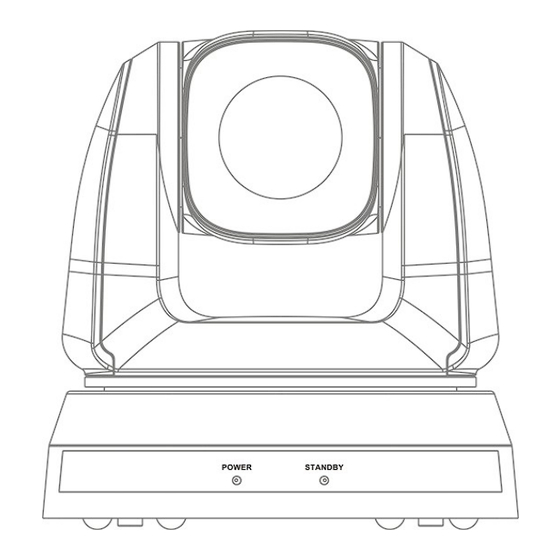
Chapter 3 Product Overview 3.1 Overview Front Back View View 1. Camera lens 2. Power LED indicator 3. Standby LED indicator 4. DVI output 5. Component output 6. Power input 7. IR SELECT 8. OUTPUT Switch 9. Camera Address Selectors 10.RS-232 output 11. -
Page 7: Chapter 4 Instruction For Installation
Chapter 4 Instruction for installation 4.1 Preparation before installation Installation and connection of HD camera requires special skills. To install by yourself, please follow necessary steps, ensure steady and tight installation of the device, and pay attention to your safety to avoid any accident. 4.1.1 Ensure the safety of the installation environment. - Page 8 Installation steps 4.2.1.2 Please adjust DIP switch at first prior to installation. <Remark>Please refer to Chapter 7 DIP Switch Setting for the relevant descriptions on DIP switch. 2. Place the camera on a flat desk directly to ensure the normal vertical and horizontal operation of the machine.
- Page 10 4.2.2.4 Size Diagram 1. Metal plate B - ceiling side Metal plate B locking Metal plate B locking screw bolt M3 threaded hole M3 threaded M3 threaded hole hole Metal plate B - ceiling side...
- Page 11 2. Metal plate A - machine side Metal plate A locking screw Metal plate A - machine side 3. Bottom of machine...
- Page 12 4.2.2.5 Precautions for installation 1. Before installation, please confirm the orientation of the machine relative to the object to be captured. 2. It is recommended that the machine should be set at a distance of more than 1 meter away from the object to be captured. Please adjust for a best distance according to the magnification of the lens.
- Page 13 1 meter↑ Computer 3. The machine (including metal plates) is weighed at about 2.5 kg. If it is to be installed on the ceiling, please use the hanger that has obtained UL security approval to prevent the machine from falling down. 4.
-
Page 14: Connecting The Device
(2) Please reserve the hole for the connecting wires of the camera 4. Combine the metal plate A and the metal plate B Push the metal plate A up to the ceiling and then to the right to latch the metal plate B (2) Fix with 3 M3 screws 4.2.2.7 How to remove 1. - Page 15 Connecting to a HDTV/computer monitor (DVI) 4.3.1.1 DVI cable Monitor or HDTV Connecting to a TV (C-Video) 4.3.1.2 C-Video Cable Connecting to a HDTV (3G-SDI) 4.3.1.3...
- Page 16 SDI Cable HDTV Connection to the device for image output 4.3.1.4 Component adaptor HDTV 4.3.2 Controlling cameras with the computer Connecting to one computer for connection between 4.3.2.1 cameras (RS-232 in/out)
- Page 17 <Remark>With RS-232 in/out, at most 7 cameras can be connected. Connecting to one computer for connection between 4.3.2.2 cameras (RS-422) <Remark>Please refer to 7.2 RS-422 connection for the RS-422 connection instructions. <Remark>With RS-422, at most 7 cameras can be connected.
-
Page 18: Chapter 5 Remote Control And Setting Menu
Chapter 5 Remote Control and Setting Menu 5.1 Functions of remote control <Remark>The below functions are listed alphabetically. Item Description Move the lens ,,, Back Light Turn on/off back light compensation Camera Choose camera 1 ~ 3 select Focus- Turn on manual focus to adjust the Manual / focal length Far/Near... -
Page 19: Setting Menu
5.2 Setting menu <Remark>Press [Menu] on the remote control to enter the setting menu; the bold underlined values in the following table are defaults. Level Level Level Function Descriptions Major Minor Items Adjustment Items Values 1. Full Auto 2. Shutter Pri 3. - Page 20 1/120 1/120 1/100 1/100 1/90 1/75 1/60 1/50 1/30 1/25 1/15 1/12 1. F1.6 2. F2 3. F2.2 4. F2.7 5. F3.2 6. F3.8 7. F4.5 Iris Pri 8. F5.4 IRIS priority setting 9. F6.3 10. F7.8 11. F9 12. F11 13.
- Page 21 60/30 50/25 mode mode 1/10000 1/10000 1/5000 1/5000 1/3000 1/3000 1/2500 1/2500 1/2000 1/1750 1/1500 1/1250 1/1000 1/1000 1/725 1/600 1/500 1/425 1/350 1/300 Manual Manually set the shutter 1/250 1/215 Speed 1/180 1/150 1/120 1/120 1/100 1/100 1/90 1/75 1/60 1/50 1/30...
- Page 22 12. F11 13. F13 14. F16 15. F18 1. 8 dB 2. 10 dB 3. 12 dB 4. 14 dB 5. 16 dB 6. 18 dB The maximum electric Gain Limit 7. 20 dB gain limit 8. 22dB 9. 24dB 10.
- Page 23 12. 8000K 13. 3000k ~ 7000k One Push ENTER One push trigger Trigger Adjustable when the white Manual Blue 0~ C~60 balance mode is set to Manual Adjustable when the white Manual Red 0~ C~60 balance mode is set to Manual Picture 4.
- Page 24 Adjustable when Image Gamma 0~ A ~3 Mode is set to Custom. Set skin tone, Adjustable Skin Tone 1~ A ~5 when Image Mode is set to Custom. Adjustable when Image Brightness 0~ A ~14 Mode is set to Custom. Adjust the contrast of the screen, Contrast...
- Page 25 NTSC LB NTSC CP NTSC SQ C-Video Image mode PAL LB PAL CP PAL SQ Video Type Select output video type YPbPr/DVI Turn on/off the prompt Prompt ON/Off information on the display System Turn on/off the infrared IR Receive ON/Off reception Control Encoder /...
-
Page 26: Chapter 6 Descriptions Of Major Functions
Chapter 6 Descriptions of Major Functions 6.1 I would like to switch camera 1. Press [Camera 1 ~ 3] on the Remote Control to select camera. ● Camera 1 ~ 3 is selected with IR SELECT. 6.2 I would like to save the current lens position data 1. -
Page 27: I Would Like To Adjust The Focal Length
6.7 I would like to adjust the focal length 6.7.1 Auto tune 1. Press [AF] on the remote control to adjust automatically. 6.7.2 Manual focus 1. Press [MF] on the remote control to turn on the manual focus function. 2. Press Focus - [+] or Focus - [-] to adjust. 6.8 I would like to adjust the focus speed 6.8.1 Adjust the AF sensitivity... -
Page 28: I Would Like To Rotate The Image
6.11 I would like to rotate the image 1. Press [Mirror] on the Remote Control to switch [Disable/Mirror/Flip/ Mirror+Flip]. 6.12 I would like to change the camera direction 1. Press [L/R Direction Set] on the remote control to switch [L/R Direction/Disable/Normal]. -
Page 29: Chapter 7 Dip Switch Setting
Chapter 7 DIP switch setting <Note>Please turn off the machine before changing DIP switch setting. 7.1 DIP SWITCH 7.1.1 OUTPUT Switch Output Mode Setting Output Mode Setting 1920x1080/60p 1920x1080/50p 1920x1080/30p 1920x1080/25p 1920x1080/60i 1920x1080/50i 1280x720/60p 1280x720/50p 1280x720/30p 1280x720/25p 1920x1080/59.94 1920x1080/59.94p 1920x1080/29.97p 1280x720/59.94p 1280x720/29.97p 7.1.2... -
Page 30: Rs-422 Connection
7.1.3 Camera Address Selector Setting Function Descriptions ID 0~7 Reserved 7.1.4 System Switch Setting Function Descriptions RS-232C/RS-422 selector DIP 1 OFF : RS-232C / ON : RS-422 Infrared signal output switch DIP 2 OFF : Off / ON : On Communication baud rate selector DIP 3 OFF : 9600 / ON : 38400... - Page 31 TXD OUT - TXD OUT + RXD IN - RXD IN + TXD IN - TXD IN + <Note> For SONY products, please connect IN+ to OUT+ For non-SONY products, it may be necessary to connect IN+ to OUT- 7.2.2 Use RS-422 Connection 1.
- Page 32 <Note> When RS-422 connection is being used, do not use RS- 232C connection.
-
Page 33: Chapter 8 Troubleshooting
Chapter 8 Troubleshooting This chapter describes problems you may encounter while using camera. If you have questions, please refer to related chapters and follow all the suggested solutions. If the problem still occurred, please contact our distributors or service center. Problems Solutions Boot without... - Page 34 3. Make sure System Switch DIP1 and DIP3 are correct. The device cannot 1. Make sure the connection is correct (RS-232/422 be controlled with Input). RS-232/RS422 2. Make sure System Switch DIP1 and DIP3 are correct.
Need help?
Do you have a question about the HDC-711 and is the answer not in the manual?
Questions and answers