Table of Contents
Advertisement
Quick Links
MANUAL DE INSTRUCCIONES Y ESQUEMAS
MANUAL OF INSTRUCTIONS AND DIAGRAMS
MANUEL D'INSTRUCTIONS ET SCHÉMA
CONTROL BOX
RSPV ECO
Speed Doors
Puertas Rápidas
Portes Rapides
Sectional Doors
Puertas Seccionales
Portes Sectionnelles
Dock Levellers
Muelles de Carga
Quai Niveleur
Sas d'etanchéité
Dock Shelters
Abrigos de Carga
Bridging Platforms
Pasarelas Móviles
Passerelles
Mesas Elevadoras
Tel. +34 972.640.620 Fax. +34 972.643.719
www.angelmir.com
info@angelmir.com
Advertisement
Table of Contents

Summary of Contents for Angel Mir RSPV ECO
- Page 1 MANUAL DE INSTRUCCIONES Y ESQUEMAS MANUAL OF INSTRUCTIONS AND DIAGRAMS MANUEL D’INSTRUCTIONS ET SCHÉMA CONTROL BOX RSPV ECO Speed Doors Puertas Rápidas Portes Rapides Sectional Doors Puertas Seccionales Portes Sectionnelles Dock Levellers Muelles de Carga Quai Niveleur Sas d’etanchéité Dock Shelters...
-
Page 2: Table Of Contents
3. DESCRIPTION........................... 3 3.1. EXTERNALLY MOUNTED COMPONENTS: ................3 3.1. INTERNALLY MOUNTED COMPONENTS:................4 4. GENERAL SPECIFICATION OF THE RSPV ECO CONTROL PANEL ........ 5 5. PROGRAMMING THE AUTO-TIMED RETURN ............... 6 6. BAND RADIO INTRODUCTION ....................7 6.1. RECEIVER ............................ 7 6.2. -
Page 3: Instructions
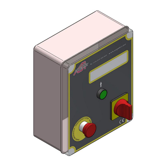
You should keep a record of all services or repairs carried out on the door. DESCRIPTION The RSPV ECO control stand is a stand designed to control automatic doors using 200-240 V. triphasic V .With power supply at 200-240 single phase but will not exceed the 3/4HP. -
Page 4: Internally Mounted Components
3.1. INTERNALLY MOUNTED COMPONENTS: Inside the stand is a programmable relay circuit board for speed doors designed for intensive use, which has different inputs and outputs for the door drive, the fault control and the door drive counters. . The voltage circuit board is independent, with an output which has a frequency variator which allows the speed of the raising and lowering of door to be programmed independently guaranteeing a long usage life. -
Page 5: General Specification Of The Rspv Eco Control Panel
GENERAL SPECIFICATION OF THE RSPV ECO CONTROL PANEL SUPPLY 200-240v three phase at 50/60 Hz. plus EARTH TRANSFORMER Primary: 200-240v. A.C. Secondary : 24 v D.C. Power: 1.2A POWER CIRCUIT FREQUENCY VARIATOR Supply of: 200-240 V A.C. monophasic. (Manual speed controller inside the control unit). -
Page 6: Programming The Auto-Timed Return
Go back to step nº 2 and nº 3, the screen will flash and by pushing keys 2 or 3 (lower or raise) the time can be changed, when the time has been set press the green key (OK) and exit by pressing key Nº1 until you exit to the screen showing Angel Mir. REMEMBER: The factory set time is in seconds ( 01.0 seconds). -
Page 7: Band Radio Introduction
BAND RADIO INTRODUCTION Radio band system is designed to be installed along with band security garage door installations. This system enables the guard band connection - wireless control unit. 6.1. RECEIVER CONNECTIONS Terminals Function Cable connected Power supply 12/24V ac / dc (+) Power supply 12/24V ac / dc (-). -
Page 8: Transmitter
6.2. TRANSMITTER RADIOBAND/TA Safety edge connection Programming button RADIOBAND/TBX CONNECTIONS Function Function 2 terminal block B1 Connecting band resistive touch N.C closed safety contact Selector jumper No points for resistive band Dotted for closed contact Led Normally OFF Power. To set the receiver 6.3. -
Page 9: Electrical Circuit Diagram
ELECTRICAL CIRCUIT DIAGRAM V4.3 GB CSVAG4.014654 9 de 18... - Page 10 V4.3 GB CSVAG4.014654 10 de 18...
- Page 11 V4.3 GB CSVAG4.014654 11 de 18...
- Page 12 V4.3 GB CSVAG4.014654 12 de 18...
- Page 13 V4.3 GB CSVAG4.014654 13 de 18...
- Page 14 V4.3 GB CSVAG4.014654 14 de 18...
- Page 15 V4.3 GB CSVAG4.014654 15 de 18...
-
Page 16: Optional Opening Devices
OPTIONAL OPENING DEVICES The controller allows the use of different devices to initiate opening the door, ie loop detecters (magnetic field), radio control, motion detection, passive and active infra red and presence sensing , photocells etc or any others which has a normally open volt free contact. -
Page 17: 10. Advice On Malfunctions
10. ADVICE ON MALFUNCTIONS The door should only be repaired by installers approved by a distributer or the manufacturer and who have the necessary knowledge about all its components (the mechanics, electrics and safety systems). In the following tables are a series of things which may lead to the malfunction of the door and various possible solutions. The programmable relay has a series of warnings on the control screen that indicate the condition of the door. - Page 18 MALFUNCTION SOLUTIONS TABLE – II PROBLEM TEST CAUSE SOLUTION Lowering end-stop broken. Check that the 24v-7 is a closed contact (except if END-STOP. Fault in the Micro-Switch. the door is closed). Any of the opening signalling Check the Open button (See sect. 2). Check devices is sending a fixed opening external opening buttons and/or devices, if there are OPENING DEVICES.
Need help?
Do you have a question about the RSPV ECO and is the answer not in the manual?
Questions and answers