
Summary of Contents for btsr MATRIX TOUCH DIAPER
- Page 1 MATRIX TOUCH DIAPER MATRIX TOUCH DIAPER 2 Operating Manual Original Instructions ENGLISH Rev. 3.3 – 09 / 2024...
- Page 2 Copyright – BTSR International SpA - All rights reserved. This manual is entrusted to the users of MATRIX TOUCH DIAPER and MATRIX TOUCH DIAPER 2 systems used to control/monitor the application tension of elastic yarns on automatic diapers (or similar disposable products) production lines. You are kindly recommended to thoroughly read the instructions provided by this manual prior to connect and use the system.
-
Page 3: Table Of Contents
1 – Installation and Connections 1.1 SYSTEM POWER SUPPLY ............................. 1-1 1.2 CONNECTION TO ELECTRICAL BOX ..........................1-3 1.3 MATRIX TOUCH DIAPER INTERFACE ........................... 1-4 1.4 CONFIGURATION OF SM-DIN/MULTILOOP BOARD ....................1-5 2 – Operating Instructions 2.0 COMPATIBILITY NOTE ..............................2-1 2.1 MATRIX TOUCH DIAPER OPERATION ......................... - Page 4 SIDE BUTTON TEST ................................2-31 DATE AND TIME SET ................................2-33 INFORMATION ABOUT MATRIX TOUCH ........................... 2-34 FIRMWARE UPGRADE OF MATRIX TOUCH DIAPER AND OTHER DEVICES ..............2-36 STYLE PROGRAMMING ..............................2-37 EVENTS LOG ..................................2-52 EFFICIENCY CALCULATION MODE............................. 2-57 GRAPHICS DISPLAY ................................
-
Page 5: Introduction
Introduction... - Page 6 (or similar products) production lines with DIAPERFEEDER devices. The MATRIX TOUCH DIAPER panel, equipped on Matrix Cube, Matrix Cube 2 and Matrix Cube 3 creels, represents the standard and best interface to control MATRIX CUBE systems and generally BTSR equipment. The panel is connected to the SM-DIN/MULTILOOP control board and the parameters settled on the MATRIX TOUCH DIAPER are passed to the SM- DIN/MULTILOOP for the system working and control.
-
Page 7: Manual Objectives
Introduction MANUAL OBJECTIVES This manual has been written to provide the users of MATRIX TOUCH DIAPER system with the essential information required to: Correctly install and connect the various system components (MATRIX TOUCH DIAPER terminal, SMDIN/MULTILOOP control Board, DIAPERFEEDER devices, TFS or TS444 and TS55 or TMS sensors.) ... -
Page 8: Warranty And Manufacturer Liability
Any claim shall be notified without delay, upon discovery of any defect. In case, after carefully assessment, the claim is proven to be well-founded, BTSR shall, at its sole option, either replace or repair the defective goods. -
Page 9: Ce Declaration Of Conformity
EN 13849-2:2012 The person authorized to collect the Technical File is: Ing. M. Tomazzolli - info@btsr.com The above indications are merely for information purposes and should not be considered as an alias of the actual conformity statement subscribed and released by the Manufacturer. -
Page 10: Compliance With European Directives And Standards
Machinery Directive 2006/42/CE, with the Electromagnetic Compatibility requirement provided by EMC Directive 2014/30/UE and with the RoHS requirement provided by Directive 2011/65/UE - RoHS III. During the design and manufacturing stages of BTSR equipment, the relevant paragraphs of the following Harmonized Standards have also been used as reference and guide line. - Page 11 Introduction Page intentionally left blank MATRIX TOUCH DIAPER - vi -...
-
Page 12: Installation And Connections
Installation and Connections... -
Page 14: System Power Supply
Installation and Connections 1.1 SYSTEM POWER SUPPLY The MATRIX TOUCH DIAPER system can be supplied with electrical equipment enclosed in a box, installable on board machine, compliant with the prescriptions of the Harmonized Standard EN 60204-1:2018. The electrical box is fitted with an ON/OFF switch with “Door Locking” feature, and it provides a protection degree IP54. - Page 15 Make sure that the creel metallic frame and the electrical box itself are correctly connected to ground (PE clamp inside the electrical box and stranded wires to connect the various creel elements). MATRIX TOUCH DIAPER - 1-2 -...
-
Page 16: Connection To Electrical Box
Installation and Connections 1.2 CONNECTION TO ELECTRICAL BOX Electrical Box MCC3/MCFB/xxx/y (Standard flat version) MATRIX TOUCH DIAPER xxx= ETH (Ethernet/IP) y=M (Single phase) connection xxx= PFN (Profinet) y=T (Three phase) TMS/TS55 connection Connection of DIAPERFEEDER devices Start / Stop /... -
Page 17: Matrix Touch Diaper Interface
Installation and Connections 1.3 MATRIX TOUCH DIAPER INTERFACE The following figure shows the electrical interface (pin assignment) of MATRIX TOUCH DIAPER terminal. Tamper Battery slot Connection to electrical USB connection for Backup and firmware update Ethernet port for PC-LINK WEB DIAPER Figure 5 –... -
Page 18: Configuration Of Sm-Din/Multiloop Board
CUBE systems are totally controlled by the PLC this parameter has to be set to NO. For more details about machine PLC integration and the configuration of this parameter please refer to Machine Supplier, BTSR authorized reseller or BTSR Headquarter. - Page 19 Installation and Connections Page intentionally left blank MATRIX TOUCH DIAPER - 1-6 -...
-
Page 20: Operating Instructions
Operating Instructions... -
Page 21: Compatibility Note
All the Configuration, Parameter Setting, Data & Error Display operations, etc. can be managed by the Operator in quick and intuitive way, using the MATRIX TOUCH DIAPER control terminal. The MATRIX TOUCH DIAPER Operator interface consists of 2 main elements: Touch Screen and HOME button. Figure 6 – MATRIX TOUCH DIAPER A - Touch Screen used to select menus, functions, fields, etc. - Page 22 MATRIX TOUCH DIAPER Operation MATRIX TOUCH Calibration procedure: Switch off the Matrix touch terminal Switch on the Matrix touch terminal holding the main button. It must be visualized the sequence of the screens as indicated in the next images Keep held the main button until appears the countdown screen. Before the end the countdown, tap the screen to enter in the touch screen calibration.
-
Page 23: Navigation Throughout The Display Windows
MATRIX TOUCH DIAPER Operation 2.2 NAVIGATION THROUGHOUT THE DISPLAY WINDOWS Many configuration/parameter setting functions of MATRIX TOUCH DIAPER system require a number of parameters distributed among multiple display windows. Display window. Parameter. Parameter current value to decrease the value, ... -
Page 24: Interpretation Of Operating Screens
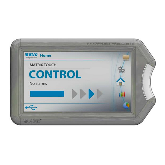
MATRIX TOUCH DIAPER Operation 2.3 INTERPRETATION OF OPERATING SCREENS System working in CONTROL status No errors detected! At least one DIAPERFEEDER device running HOME button: blue steady System working in RAMP status(as elastic yarn starts moving with EXCLUSION switch signal not yet active) ... -
Page 25: Matrix Touch Diaper Menu Structure
Network configuration 2.4 MATRIX TOUCH DIAPER MENU STRUCTURE General overview Loaded Style Status and Alarm/Warning information Circular menu Loop Mode USB connected Data Recording active or Recording active and Thread Up Settings Style Editor Home Events Log Statistics Graph In the description of the various functions, the following graphic symbols will be used:... -
Page 26: Detailed Overview
Network configuration Detailed Overview Style Editor Style Programming Home Group Editor: Status (control/alarm/error) TENSION menu Alarm/Warning dedection and details SET POINT Creel Configuration EXCLUSION TENSION Style currently loaded SWITCH MODE Loop Mode TENSION CONTROL Recording status TENSION DLY CONTROL USB connected TENS.LOW% (WARN) Navigation circular menu TENS.LOW%(STOP) TENS.LOW TIME(s) TENS.HIGH%(WARN) TENS.HIGH%(STOP) TENS.HIGH TIME(s) DF MOTION CTRL DLY Settings DF MOTION STOP TIME ... - Page 27 Network configuration Detailed Overview Graph Events Log Graphics Display Events Table Statistics Efficiency Calculation Mode MATRIX TOUCH DIAPER - 2-7 -...
-
Page 28: Network Configuration
This function allows to set the network addresses of MATRIX TOUCH PANEL. This parameter shall be done in case © MATRIXTOUCH DIAPER is working together with PC-LINK WEB DIAPER (BTSR Patent) data collection system. ATTENTION: IP address linked to PC-LINK WEB DIAPER is refereed to MATRIX TOUCH PANEL, not SM-DIN ©... -
Page 29: Creel Name
PLC on the SM-DIN. Touch the icon to display the keyboard and set the Creel Name. To delete the creel name To save the settings To go back to the previous screen page MATRIX TOUCH DIAPER - 2-9 -... -
Page 30: Creel Configuration
MMC2, MMC3…), it is necessary to click “NEXT” button and specify the Head and Tail sensor installed on. If no Matrix creel is chosen, automatically, after clicking on “NEXT” button the system comes back to the settings menu MATRIX TOUCH DIAPER - 2-10 -... - Page 31 TAIL sensors used in the current MCC. Optical sensor ISF3 (see how to configure at page 2.12) HTHS (no need a starting configuration, the creel automatically recognizes the sensors, once selected in the menu) MATRIX TOUCH DIAPER - 2-11 -...
-
Page 32: Creel Structure
This function allows you to graphically display the creel physical structure, in order to make easier the detection of the various positions. This parameter shall be done in case MATRIXTOUCH DIAPER is working together with PC-LINK WEB © DIAPER (BTSR Patent) data collection system. The example represents a creel composed of 4 positions. MATRIX TOUCH DIAPER - 2-12 -... - Page 33 The following data will then be available for reading to the PLC and to the PC-Link Web Diaper. To move to the name assignment page MATRIX TOUCH DIAPER - 2-13 -...
- Page 34 The settings of a position can be copied to other groups by using the function copy/paste. Touch copy to select the position to be copied. Such position will be indicated by the icon The following window will appear. MATRIX TOUCH DIAPER - 2-14 -...
- Page 35 Select the positions to paste the settings to. Such positions will be indicated by the icon To paste the settings to the desired positions. At this point the positions have all the same settings. To save the settings To go back to the previous screen page MATRIX TOUCH DIAPER - 2-15 -...
-
Page 36: Device Configuration And Numbering
TMS, but it is also valid in case of TS55 sensors.] Devices Set the number of elastic yarn feeding/control positions [1..8] (in this example: 4 positions, i.e. 4 DIAPERFEEDER devices and 4 TFS sensors). MATRIX TOUCH DIAPER - 2-16 -... - Page 37 Skim the touch light of the First TMS/TS55 sensor and check that: the sensor LED changes from flashing green to red. b) The MATRIX TOUCH DIAPER display shows the next sensor to be identified (number increases by 1). Skim the touch light of the Second TMS/TS55 sensor and continue with the numbering of all sensors.
-
Page 38: Head/Tail Sensor Identify
First ISF3 sensor and check that: the sensor LED changes from flashing green to red. Skim the touch light of the Second ISF3 sensor and continue with the numbering of all sensors MATRIX TOUCH DIAPER - 2-18 -... - Page 39 Head/Tail Sensor Identify NOTE: For HTHS sensor the identification procedure is not required. MATRIX TOUCH DIAPER - 2-19 -...
-
Page 40: Loop Mode
(e.g. choosing MULTILOOP the SPEED options will appear inside the STYLE menu). Also TMS/TS55 icons will change accordingly NOTE: If ONE LOOP option is selected all the alarms and warnings are referred only to the DiaperFeeder. MATRIX TOUCH DIAPER - 2-20 -... -
Page 41: Exclusion Mode
Auto: The exclusion signal is automatically activated according to the DIAPERFEEDER yarn feeding speed (to be used only in case of unavailability of BUS or external signal) Refer to section Style Programming for more details. MATRIX TOUCH DIAPER - 2-21 -... -
Page 42: I/O Configuration
STOP Output#1 (alarm signals for line stop) STOP Output#2 (warning signal) Exclude DF Off Positions (when enabled it inhibits TS-COMM error if TMS is not connected. The correspondent position have to be disabled inside style editor) MATRIX TOUCH DIAPER - 2-22 -... -
Page 43: Data Recording
DATA RECORDING This function allows you to configure the recording settings of 6 data types. The MATRIX TOUCH DIAPER system allows to record 6 different types of events: Machine Start, Machine Stop, Alarm, Spool Change, External and Periodic Event. For each event it is possible to record 100 to 2500 points [default 300] and to set a Trigger point (Trigger Set), i.e. -
Page 44: Web-Up Function
This screen indicates that the combination (TMS/TS55 and DIAPERFEEDER) No.1 is currently selected. To select other positions The red LEDs will blink on the selected combination (TMS/TS55 and DIAPERFEEDER) in order to make easier the location of devices association. MATRIX TOUCH DIAPER - 2-24 -... -
Page 45: Offset On Tms/Ts55 And/Or Diaperfeeder Devices
To start the offset function To go back to the previous screen page We remind you that, prior to confirm the offset execution, it is necessary to remove the yarn from the loading cell. MATRIX TOUCH DIAPER - 2-25 -... -
Page 46: Matrix Touch I/O Check
I/O check MATRIX TOUCH I/O CHECK Debug menu; this function allows to check touch panel parameters. MATRIX TOUCH DIAPER - 2-26 -... -
Page 47: Service Pass-Through Mode
Pass-Through mode SERVICE PASS-THROUGH MODE Debug menu; this function allows to enable communication channel with PC-LINK KTF STUDIO debug/analysis tool. MATRIX TOUCH DIAPER - 2-27 -... -
Page 48: Language Selection
Language Selection LANGUAGE SELECTION This function allows to change panel language. MATRIX TOUCH DIAPER - 2-28 -... -
Page 49: Matrix Touch Backup
ATTENTION : Backup and restore are directly correlated to the MATRIX TOUCH connected with USB. Generally, backup is suggested on similar creels (equal number of elastics) and it has to be performed between units with the same firmware version MATRIX TOUCH DIAPER - 2-29 -... -
Page 50: Bus Message Log
Data is stored in Volatile memory (exiting the menu the same data will not be available at the next access) Pressing DECODE button it is possible to translate the data according to the communication protocol. MATRIX TOUCH DIAPER - 2-30 -... - Page 51 Bus Message Log MATRIX TOUCH DIAPER - 2-31 -...
-
Page 52: Side Button Test
Side Button Test SIDE BUTTON TEST This function allows to test the correct functioning of the side button. MATRIX TOUCH DIAPER - 2-32 -... -
Page 53: Date And Time Set
Note 1: Date and time to be checked at fist panel power on or if the panel is left switched off for long time (if necessary check the tamper battery). Note 2: When PC-LINK WEB DIAPER in installed the Date and Time is automatically synchronized with main data collection servers MATRIX TOUCH DIAPER - 2-33 -... -
Page 54: Information About Matrix Touch
Information about Matrix Touch INFORMATION ABOUT MATRIX TOUCH This function allows you to detect the terminal Firmware versions. This information shall be communicated to BTSR Service Department when requiring technical support to solve specific problems. MATRIX TOUCH 1 MATRIX TOUCH 2 NOTE: On the bottom right of the screen of MATRIX TOUCH 2 is possible to show the voltage delivered and the temperature of the system. - Page 55 Information about Matrix Touch NOTE: Check that the tamper battery voltage is always around 3V. MATRIX TOUCH DIAPER - 2-35 -...
-
Page 56: Firmware Upgrade Of Matrix Touch Diaper And Other Devices
It is possible to upgrade MATRIX TOUCH DIAPER panel itself, TMS sensors, SMDIN control board and DIAPERFEEDER devices using MATRIX TOUCH DIAPER specific feature and a USB key (empty key and FAT32 file system are recommended). As USB Key with devices firmware is inserted in the panel, the main folder appears and it is possible to choose the related upgrade. -
Page 57: Style Programming
All the connected DIAPERFEEDER devices can be configured with the same parameters otherwise it is possible to create multiple device groups (sections), configuring each section with different parameters in order to increase the system flexibility. It is possible to configure up to 100 different Styles. MATRIX TOUCH DIAPER - 2-37 -... - Page 58 If activated (ON), it indicates the minimum tension value, below which an alarm will be generated (-1 to -100 % of the setpoint value) (OFF = control disabled) [1…100, Default 10] 7 TENS. LOW% (STOP) MATRIX TOUCH DIAPER - 2-38 -...
- Page 59 TMS/TS55 sensor itself when the yarn still actuates tension sensors with load inside the programmed tension range. NOTE2: DF MOTION CTRL DLY and TMS MOTION CTRL DLY parameters allow to detect a yarn disabled that is moving. MATRIX TOUCH DIAPER - 2-39 -...
- Page 60 TENS.LOW TIME (s) = 5 s Tension [g] NO ALARM ALARM NO ALARM Time [s] Example of TENS. LOW Alarm generation (same logic is valid for TENS. HIGH Warning and Alarm and for TENS. LOW Warning) MATRIX TOUCH DIAPER - 2-40 -...
- Page 61 (not visible if HTHS is chosen) 6 IS3F SWITCH COUNT 7 IS3F DELAY CTRL (s) In case Matrix Cube 1, 2 or 3 and HTHS are selected: no parameters available, no need of sensor parameters programming MATRIX TOUCH DIAPER - 2-41 -...
- Page 62 Prefeeder is 50% and pre-tensioning keeps a 100% of elastic elongation. 15 PFD-DF STRETCH Optional devices paramenter. RANGE Control of stretch regulation range of Prefeeder. Default value is 100 corresponding to a range ±10%. MATRIX TOUCH DIAPER - 2-42 -...
- Page 63 -1 to -100 % of the setpoint value) [1…100, Default Running time with speed SPEED LOW% after which an alarm 7 SPEED LOW TIME (s) will be generated [1.0…60.0, Default 10.0] [s] MATRIX TOUCH DIAPER - 2-43 -...
- Page 64 NO ALARM/ WARNING WARNING Speed [m/min] WARNING Time [s] Example of SPEED HIGH Alarm/Warning generation (same logic is valid for SPEED LOW Alarm/Warning) To save the settings To go back to the previous screen page MATRIX TOUCH DIAPER - 2-44 -...
- Page 65 The Group just created has to be assigned to devices for the correct system working; please refer to the following section Touching the indicated field you may toggle among. To select lowercase letters To select numbers and symbols To select again capital letters MATRIX TOUCH DIAPER - 2-45 -...
- Page 66 The style is now stored into the database. To display the possible options To edit the style To erase the style To load the style to the devices. When a style is loaded, the checkmark appears next to the name: MATRIX TOUCH DIAPER - 2-46 -...
- Page 67 The number of devices matched to the group is indicated in brackets (in this example: 4). To add a new group to the style. Execute the same operations carried out for the first group. MATRIX TOUCH DIAPER - 2-47 -...
- Page 68 Selecting the group B and the devices 2 and 4, it is possible to match the new group to such devices as shown on the picture below. To display the possible options of the group To edit the group To erase the group is selected, the following window appears: MATRIX TOUCH DIAPER - 2-48 -...
- Page 69 Style Programming To confirm the erasing To cancel the erasing Removal of the matching To remove the matching group/devices. The following window will appear: To confirm To go back to the previous screen page MATRIX TOUCH DIAPER - 2-49 -...
- Page 70 Style Programming Turning off a device To turn OFF/ON a device: Device OFF A dedicated message on DIAPERFEEDER screen will be displayed and device key buttons will turn from green to red. Adding a style MATRIX TOUCH DIAPER - 2-50 -...
- Page 71 If the name set for the style is already present inside the database, then the following window appears: When a style is loaded, the previously loaded style is automatically unloaded. If the active style is changed, the style will be automatically loaded after SAVE command. MATRIX TOUCH DIAPER - 2-51 -...
-
Page 72: Events Log
For each event a number of graphs that can be configured by the user with different options are available. To display the graph of an event it is possible to touch either the label of the event itself or the symbol of the magnifier. MATRIX TOUCH DIAPER - 2-52 -... - Page 73 To select a different parameters: It is also possible to select one individual parameter by changing the check selections: By selecting All, one individual parameter for all the different positions will be displayed on the graph. MATRIX TOUCH DIAPER - 2-53 -...
- Page 74 From the firmware 1.0.45 new events record logic was inserted. When the machine stop is caused by BTSR system an «ALARM» event is recorded. The elastic (or elastics) that generated the alarm is highlighted in red in the graphic page and the alarm name is displayed in the top-right part of the graphic.
- Page 75 In case of simultaneous events it will be displayed the first (event root cause) On MCC creel the SPOOL CHANGE event will be recorded only when the machine is running (Diaperfeeder motor is turning on the same elastic strand) MATRIX TOUCH DIAPER - 2-55 -...
- Page 76 It is available the possibility to trigger the EXTERNAL EVENT pressing BTSR Logo and Right button simultaneously (the BTSR Logo will blink during recording). It works only when USB key is not inserted. When inserted the USB KEY is possible to capture a snapshot of the current screen and memorize in the local storage of the USB. The same feature is...
-
Page 77: Efficiency Calculation Mode
Using the arrows it is possible to scroll the screen page to display the other errors categories. icon allows you to clear the errors. MATRIX TOUCH DIAPER - 2-57 -... -
Page 78: Graphics Display
Introduced reference speed value, that can be set manually (MANUAL), calculated by the system (AUTO) or received from PLC (EXT.-FIELBUS). Used for Speed Low Warning / Alarm to monitor the process, visible in the panel main page and in the histogram view. MATRIX TOUCH DIAPER - 2-58 -... - Page 79 It is also possible to select a position touching any point along the column related to the desired position. For instance, to select position 3: It is also possible to have evidence about status MATRIX TOUCH DIAPER - 2-59 -...
- Page 80 It is possible to show in real time the data for each positions of tension and Speed. It is an alternative view of the histogram. Is it also possible to select a specific positions and showed the data in real time of DF tension and speed. MATRIX TOUCH DIAPER - 2-60 -...
- Page 81 Graphics Display MATRIX TOUCH DIAPER - 2-61 -...
-
Page 82: Error And Warning Messages
Error and Warning Messages... -
Page 83: Matrix Touch Error And Warning Messages
3.1 MATRIX TOUCH ERROR AND WARNING MESSAGES During the normal operation, the MATRIX TOUCH DIAPER terminal display will show CONTROL in the Status panel. In case of errors or failure, the CONTROL indication will be replaced by a specific error message or failure and the position where the error occurred. - Page 84 Solution 1: Motion detected on is, on the contrary, running. Error related DIAPERFEEDER/TMS position in to MOTION CONTROL setting; it activates stand by, please remove the the STOP output and stops the machine. elastic completely MATRIX TOUCH DIAPER - 3-2 -...
- Page 85 Solution 2: Check if the elastic comes freely from the spool and Check the usage conditions of the systems. if there are abnormal work condition , press + button on Diaperfeeder and check if the motor turns freely MATRIX TOUCH DIAPER - 3-3 -...
- Page 86 Solution 1: Reset the alarm overcurrents locally on DIAPERFEEDER. Solution 2: Check the supply voltage, if the problem persists, contact your BTSR reseller Maximum limit of tension correction reached on MULTILOOP mode Related to parameter TENSION LIMIT DIAPERFEEDER Supply voltage lower than Solution 1: Reset the alarm 15 VDC.
-
Page 87: Warnings Detected During The System Operation
This value is set by default at 12 cN. Solution 2: If the ALARM persist chech the electrical connections, if the ALARM persist replace the replace the TMS. Contact your BTSR reseller MATRIX TOUCH DIAPER - 3-5 -... - Page 88 Solution 2: Lost of efficiency of related to TMS sensor. pulleys between DIAPERFEEDER It activates the WARNING output without and TMS or wrong position of the stop the machine elastic or wrong parameters combination MATRIX TOUCH DIAPER - 3-6 -...
- Page 89 Error Messages Solution 1: Update to the latest Calibration error: Check the correct firmware released operation of the HOME button. Solution 2: Replace the HOME button and contact your BTSR reseller MATRIX TOUCH DIAPER - 3-7 -...
-
Page 90: Additional Information
Additional Information... -
Page 91: Components Overview
4.1 COMPONENTS OVERVIEW 4.1.1 SM-DIN/MULTILOOP Interface PROFIBUS Interface(*) Machine Interface (INPUT) Power Supply ETHERNET interface Machine Interface (OUTPUT) (*) option on demand TMS/TS55 chain Max 10 DIAPER FEEDER devices DIAPER FEEDER chain 10 TMS/TS55 sensors MATRIX TOUCH DIAPER - 4-1 -... - Page 92 STOP output (normally open contacts) 1 A 30 VDC 0 – 24 VDC Inputs VIL Max 1.2 VDC VIH Min 5 VDC Operating temperature range +10° / +60° C Storage temperature -25° / +85° C Dimensions 138,5x124x35 mm MATRIX TOUCH DIAPER - 4-2 -...
- Page 93 Connector for TFS tension sensor connection SM/IN - SM/OUT Connectors for DIAPERFEEDER devices daisy chain connection Connector available for future expansions UNICO Connector for intelligent accessory connection IS3.. Connector for spool change sensor connection MATRIX TOUCH DIAPER - 4-3 -...
- Page 94 Operating temperature range 10° - 60 °C Storage temperature -25° - +85° C Tension range 0 / full scale Useful tension range 0% - 95% full scale Max applicable tension 10 times the full scale value MATRIX TOUCH DIAPER - 4-4 -...
- Page 95 Programmable alarms 0.1 ÷ 25 sec. Dimensions 220 x 86 x 98 mm Operating temperature range 10° - 60 °C Storage temperature -25° - +85° C Tension range 0 / full scale IP degree IP54 MATRIX TOUCH DIAPER - 4-5 -...
- Page 96 0 - full scale Useful tension range 0% - 95% full scale Max applicable tension 10 times the full scale value Drift error 0.05% / °C Repeatability error 0.5% Max linearity error 2% (0 - full scale) MATRIX TOUCH DIAPER - 4-6 -...
- Page 97 Max applicable tension 10 times the full scale value Drift error 0.05% / °C Repeatability error 0.5% Max linearity error 2% (0 - full scale) Signaling With integrated LEDs Dimensions 50 x 25 x 12.5 mm MATRIX TOUCH DIAPER - 4-7 -...
- Page 98 -25° - +85° C HTHS Sensor (spool change detection) Technical Characteristics Power supply voltage 12 Vdc ± 20% Power supply current 20 mA (max) Operating temperature range 10° - 60 °C Storage temperature -25° - +85° C MATRIX TOUCH DIAPER - 4-8 -...
-
Page 99: Functions And Firmware Version Details
Additional Information 4.2 FUNCTIONS AND FIRMWARE VERSION DETAILS SMDIN/MULTILOOP/ETH – PFN Firmware Release Table and Matrix Touch Diaper Compatibility MTX/TOUCH/DIAPER & Firmware Item Available functions MTX2/TOUCH/DIAPER version Compatible version First release Modifications on Communication Protocol (refer to dedicate documentation) Generic Optimization and bug fix... - Page 100 15.5 detection Modification of DF tension average visualization on MATRIX TOUCH panel graphics Removed UNDERFLOW alarm on disabled positions 16.1 Fix of setting for reference speed value to be displayed on Matrix Touch panel MATRIX TOUCH DIAPER - 4-10 -...
- Page 101 Changed the TS55’s led modality when ACTD optional device for yarn-hold function it’s connected (elastics trapper system). 17.9 Introduced TS55 firmware upgrade from Matrix Touch Diaper panel and FTP. Introduced the warning FBUS OVER generated in case of unexpected functions received from PLC.
- Page 102 DF display. Added Function for DF and TMS led blink green-red as the position is in alarm, only for alarms generated by BTSR local logic (enable-disable available in SMDIN menu) TMS led is set red when position is disabled...
- Page 103 MTX/TOUCH/DIAPER 1.0.00 1.0.00 1.0.10 1.0.10 1.0.10 1.0.27 1.0.32 1.0.40 1.0.40 1.0.46 15.40 15.50 16.10 16.20 16.40 16.90 17.10 17.10 – 17.80 – 17.90 17.90 17.90 18.10 10.0 18.40-18.60 10.1 18.70 10.2 18.70-19.00 10.6 19.70 MATRIX TOUCH DIAPER - 4-13 -...
- Page 104 DISTRIBUTOR BTSR International S.p.A. Via S. Rita 21057 OLGIATE OLONA (VA) Tel. 0331-323202 Fax 0331-323282 Internet: www.btsr.com REV. 3.3 – 09/24...
Need help?
Do you have a question about the MATRIX TOUCH DIAPER and is the answer not in the manual?
Questions and answers