
Summary of Contents for AZ-Delivery SG90
- Page 1 Welcome! Thank you very much for purchasing our AZ-Delivery Micro Servo Motor SG90. On the following pages, we will introduce you to how to use and setup this handy device. Have fun!
- Page 2 Areas of application These servos are used in model building projects to provide precise control movements. They are suitable for applications where precise motion controls are required. Required knowledge and skills Installation and commissioning should be carried out by people with basic knowledge of model making or manual skills. Knowledge of handling control electronics and mechanical components is required.
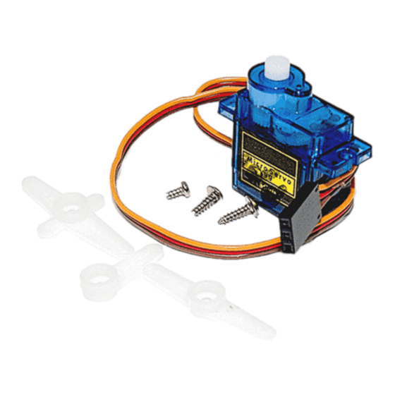
- Page 4 Servo motor introduction A servo motor is a special device containing a DC motor (high speed, low torque), feedback electronics (integrated H-Bridge) with potentiometer and a set of gears.
- Page 5 The operation of the servo motor can be described by the diagram below: A servo motor accepts DC voltage in form of pulses (desired position), usually created by microcontroller using PWM (Pulse Width Modulation) and output shaft rotation to the desired position. When the DC motor is at stop, it means the motor shaft and potentiometer knob are in its equilibrium position.
-
Page 6: Pwm - Pulse Width Modulation
PWM – Pulse Width Modulation PWM toggles the output of microcontroller ON and OFF very quickly, so quickly that motor which is attached to the output of microcontroller can’t react fully. The result is that the motor attached to the output sees a voltage that is proportional to the average percent the time that the microcontroller spends with its output on. - Page 7 All PWM does is that it simulates analog DC voltage. By changing the duty cycle we change the amplitude of this simulated analog DC voltage. So because the limits of PWM signal are 0V and 5V, duty cycle of 50% is equal to the 2.5V DC, and duty cycle of 25% is equal to the 1.25V DC.
- Page 8 For example image below (for period of 20ms), on the left duty cycle is 1ms = 1000us, which is 5%, in the middle duty cycle is 1.25ms = 1250us, which is 6.25%, and on the right, duty cycle is 2ms = 2000us, which is 10%. The exact duty cycle could vary per servo motor.
- Page 9 Technical specifications of MG996R » Operating voltage: 4.8V - 6V » Stall torque: 1.8kgf*cm (4.8V) » Operating speed: 0.12s/60º (4.8V) » Running current: 100mA - 250mA » Stall current: 360mA (6V) » Dead band width: 1µs » Rotation: 0º - 180º »...
- Page 10 motor. It is better to have separate power supply for the logic and for the actuators! Connectiong the servo motor with Atmega328p Servo pin > Mc pin Yellow pin > D3 Blue wire Brown (or black) pin > GND Black wire Servo pin >...
- Page 11 Brown (or black) pin > GND or 0V Black wire You can connect yellow pin of the servo motor to any PWM pin on Atmega328p board. There are six PWM outputs, labeled with "~" sign in the name of digital output: 3, 5, 6, 9, 10 and 11. Sketch The library for servo motors, comes preinstalled with Arduino IDE.
- Page 12 Connectiong the servo motor with Raspberry Pi Servo motor pin > Raspberry Pi pin Yellow pin > GPIO21 [pin 40] Blue wire Brown (or black) pin > GND [pin 14] Black wire Servo motor pin > External Power supply Red pin >...
-
Page 13: Script Example
Brown (or black) pin > GND or 0V Black wire Script example If you don’t already have installed “RPi.GPIO” library, here is how to do it. Start your Raspberry Pi, and open terminal, then run these commands. First you have to update Raspbian by running: sudo apt-get update &&... - Page 14 changeDT(x): 2.0: p.ChangeDutyCycle(x) print("{} degrees".format(x)) elif 7.0: p.ChangeDutyCycle(x) print("{} = 90 degrees".format(x)) elif 11.5: p.ChangeDutyCycle(x) print("{} = 180 degrees".format(x)) else: p.ChangeDutyCycle(x) print("{}".format(x)) print("[press ctrl+c to end the script]") try: while True: range(19): changeDT(x) time.sleep(time_pause) 11.5 range(19): changeDT(x) time.sleep(time_pause) except KeyboardInterrupt: p.stop()
- Page 15 GPIO.cleanup() In order to calculate duty cycle we need to do the following: Because the frequency is 50Hz, one period lasts for 20ms. Duty cycle of 0.4ms is equal to the : (0.4ms / 20ms) * 100 = 2% - and this is equal to 0° position of arm connected to the servo motor.
- Page 16 If you are looking for the high quality microelectronics and accessories, AZ-Delivery Vertriebs GmbH is the right company to get them from. You will be provided with numerous application examples, full installation guides, eBooks, libraries and assistance from our technical experts.
Need help?
Do you have a question about the SG90 and is the answer not in the manual?
Questions and answers