JIKONG JK-B2A25S-RP Operation And Maintenance Manual
Hide thumbs
Also See for JK-B2A25S-RP:
- Operation and maintenance instruction (34 pages) ,
- Specification and operation manual (26 pages)
Advertisement
Quick Links
Advertisement

Related Manuals for JIKONG JK-B2A25S-RP

Summary of Contents for JIKONG JK-B2A25S-RP
- Page 1 JK - B2A25S - RP Operation and Maintenance Manual...
- Page 2 contents 1 Overview ............................4 2 Main technical parameters ....................4 technical indicators ..............................................Use environmental conditions 3 Connector and Interface Description ................2 Front panel connectors, LEDs Lamp Position Description ..........Front Panel Connector, Illuminated Switch Definition Description ......................... Product appearance ................................
- Page 3 JK - B2A25S - RP The battery management system is a battery management system tailored for large-capacity series lithium battery packs. Should The sy s t e m is suitable for battery packs of 3 to 25 strings, and has the functions of battery protection, voltage acquisition and voltage equalization.
- Page 4 ◆ Single voltage range 1 V ~ 4.5 V , the accuracy is ± 5 mV ; ◆ With coulomb counter function ; ◆ Suitable for large-capacity ternary, lithium iron, lithium titanate and other lithium battery packs; ◆ Bluetooth communication function, equipped with APP , you can check the battery status in real time;...
- Page 5 JK - B2A25S - RP _ _ _ _ Battery Management System Operation and Maintenance Manual Operating temperature range: -20 ℃ ~ 70 ℃; b ) Power Requirements: 16 V ~ 100 V , can use battery self-powered or external power supply. c ) Power consumption : the maximum power consumption of the protection board is 1.5 W (Excluding relay power consumption), shutdown power consumption 20 mW .
- Page 6 JK - B2A25S - RP _ _ _ _ Battery Management System Operation and Maintenance Manual Table 1 Connector Definitions Total negative electrode of battery The first string of battery positive The second string of battery positive B3 _ 3rd string battery positive B4 _ 4th battery positive pole The 5th battery positive pole...
- Page 7 JK - B2A25S - RP _ _ _ _ Battery Management System Operation and Maintenance Manual B 18 No. 18 String battery positive B 19 No. 19 String battery positive B 20 20th _ String battery positive B 21 21st _ String battery positive B 22 No.
- Page 8 JK - B2A25S - RP _ _ _ _ Battery Management System Operation and Maintenance Manual shunt positive Shunt Negative Precharge switch negative Precharge switch positive Discharge switch negative Discharge switch positive charge switch negative C ++ C ++ charging switch positive The power supply of the protection board is positive reserved pins...
- Page 9 JK - B2A25S - RP _ _ _ _ Battery Management System Operation and Maintenance Manual Heat + heating switch positive Heat + heating switch positive Protection board power supply negative ACC - ignition switch- ACC + ignition switch + Charge detection- 485_B / CAN_L _ _ _ , default CAN_L _ B / L...
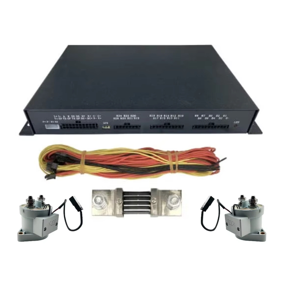
- Page 10 JK - B2A25S - RP _ _ _ _ Battery Management System Operation and Maintenance Manual picture 2 JK - B 2 A 25 S - RP Rendering - front JK - B2A25S - RP The equalizer size is 188.6 mm × 94 mm × 23.5 mm , the shape and size of the mounting hole are shown in the figure 3 shown.
- Page 11 JK - B2A25S - RP _ _ _ _ Battery Management System Operation and Maintenance Manual picture 3 JK - B 2 A 25 S - RP Dimensions Standard shunt uses up to 500 A Current, full scale 75 mv dropout. The dimensions are shown in Figure 4 .
- Page 12 JK - B2A25S - RP _ _ _ _ Battery Management System Operation and Maintenance Manual Unpacking inspection and precautions are as follows: The packing box, equalizer, etc. need to be handled with care, and try not to be inverted; Before unpacking, pay attention to whether the packaging is in good condition, if there is no impact mark, whether there is damage, etc.;...
- Page 13 JK - B2A25S - RP _ _ _ _ Battery Management System Operation and Maintenance Manual Figure 6 20 -series battery wiring diagram 1 6 The wiring method of the battery string system is shown in Figure 7 . Figure 7 16 -series battery wiring diagram By scanning the QR code shown in Figure 8 , you can obtain the mobile APP matching the product (Android), IOS mobile phone user...
- Page 14 JK - B2A25S - RP _ _ _ _ Battery Management System Operation and Maintenance Manual App available directly in the Apple Store Store Search for " Jikong BMS " to download and install. Figure 8 Mobile APP Connect QR code...
- Page 15 JK - B2A25S - RP _ _ _ _ Battery Management System Operation and Maintenance Manual APP for the first time You will be prompted to enter a password. The default password of the device is " 12 3 4 ", APP after the device is connected The password will be automatically recorded, and you don't need to enter the password for the next connection, open the APP after automatic Connection, password input interface as shown in Figure 10 .
- Page 16 JK - B2A25S - RP _ _ _ _ Battery Management System Operation and Maintenance Manual picture 9 Device Scan Figure 1 0 Password input Change password and name After the device is connected, click the pen icon on the right side of the device list to modify the device name and password.
- Page 17 JK - B2A25S - RP _ _ _ _ Battery Management System Operation and Maintenance Manual picture 12 Password picture 11Name Modification modification...
- Page 18 JK - B2A25S - RP _ _ _ _ Battery Management System Operation and Maintenance Manual 5.3.2 _ _ real-time status interface is shown in Figure 13 . picture 13 Real-time status display On the real-time status page, you can view the switch status, charging current, discharging current, temperature display, protection alarm, single Body voltage , total battery voltage, maximum voltage difference, cell average voltage, balance state, balance current, balance line resistance...
- Page 19 JK - B2A25S - RP _ _ _ _ Battery Management System Operation and Maintenance Manual battery . Please set this value accurately before use, otherwise the protection board will not work. works fine. This value is the design capacity of the battery .
- Page 20 JK - B2A25S - RP _ _ _ _ Battery Management System Operation and Maintenance Manual When the balance switch is turned on, when the maximum voltage of the battery pack is Equilibration begins when the difference exceeds this value and ends when the differential pressure falls below this value.
- Page 21 JK - B2A25S - RP _ _ _ _ Battery Management System Operation and Maintenance Manual Figure 1 4 parameter settings "Cell undervoltage protection" refers to the cut-off voltage of the cell, as long as the voltage of any cell in the battery pack is lower than this value, the ' Single undervoltage alarm' is generated, and the protection board closes the discharge MOS at the same time , the battery cannot be discharged at this time, but can only be charged.
- Page 22 JK - B2A25S - RP _ _ _ _ Battery Management System Operation and Maintenance Manual "Single overcharge voltage" refers to the saturation voltage of the battery cell. As long as the voltage of any single cell in the battery pack exceeds this value, the ' Single overcharge alarm' is generated, and the protection board turns off the charging MOS at the same time , the battery cannot be charged at this time, but only discharged.
- Page 23 JK - B2A25S - RP _ _ _ _ Battery Management System Operation and Maintenance Manual after the "discharge After the " current release" time, the protection board releases the "discharge overcurrent alarm", and re-opens the discharge MOS . Example: Set "Maximum Discharge Current" to 100 A , "Discharge overcurrent delay"...
- Page 24 JK - B2A25S - RP _ _ _ _ Battery Management System Operation and Maintenance Manual Warning while the protection board turns off the charging MOS . After the alarm is generated, when the temperature is higher than "charging low temperature recovery", the protection board will release the "charging low temperature protection"...
- Page 25 JK - B2A25S - RP _ _ _ _ Battery Management System Operation and Maintenance Manual picture 15 BMS control page 2 for fault reasons and treatment . surface 2 Fault causes and solutions...
- Page 26 The common faults, possible causes and solutions are listed above . If the fault is still not solved, please contact Chengdu Solved by Jikong Technology Co., Ltd. The battery management system itself does not have high voltage and will not cause electric shock to the body.
- Page 27 JK - B2A25S - RP _ _ _ _ Battery Management System Operation and Maintenance Manual When welding on equipment, make sure that the tip of the soldering iron is grounded; If it is unavoidable to use a non-conductive container, place the PCB Before must be packaged with conductive material, these Materials include, for example, conductive foam rubber or ordinary aluminum foil .
- Page 28 JK - B2A25S - RP _ _ _ _ Battery Management System Operation and Maintenance Manual 2.500 _ 2.800 _ Cell undervoltage protection 2.650 _ 3.200 _ Single unit undervoltage protection recovery 3.6 5 4.2 _ Cell overcharge voltage 3.6 _ 4.1 _ Cell overcharge protection recovery...
- Page 29 JK - B2A25S - RP _ _ _ _ Battery Management System Operation and Maintenance Manual Discharge over °C temperature protection temperature Discharge over- °C temperature recovery temperature -2 0 -2 0 Charging low °C temperature protection temperature - 10 - 10 Charging low °C...
Need help?
Do you have a question about the JK-B2A25S-RP and is the answer not in the manual?
Questions and answers