
Summary of Contents for makute TR001-8
- Page 2 Trimmer TR001-8...
- Page 3 .com grounded. If operating the power tool in Trimmer damp locations is unavoidable, a Ground TR001-8 Fault Circuit Interrupter must be used to supply the power to your tool. Electrician’s Rated Voltage 220-240V~50/60HZ rubber gloves and footwear will further...
- Page 4 .com switch “ON” invites accidents. cutting tools sharp and clean. Properly Remove adjusting keys or wrenches maintained tools, with sharp cutting edges before turning the tool “ON”. A wrench are less likely to bind and are easier to or a key that is left attached to a rotating control.
- Page 5 .com with product replace strict adherence to Watch for vibration or wobbling that could router safety rules. If you use this tool indicate an improperly installed bit. unsafely or incorrectly, you can su er Take notice of the direction of serious personal injury.
-
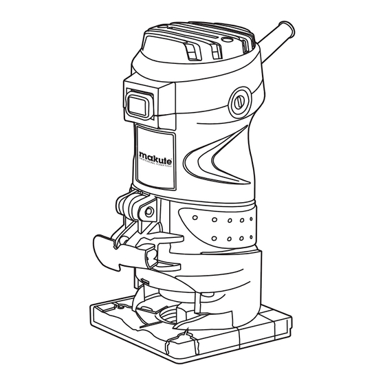
Page 6: Function Description
.com damage or injury resulting from such cases roller. After adjusting, tighten the lock lever of misuse. rmly to secure the tool base. ASSEMBLING Installing and removing trimmer bits CAUTION: Always ensure that the router is switched o and unplugged from the mains supply before installing or removing a router bit. - Page 7 .com Template Guide 1. Work piece 2. Bit revolving direction 3. Feed direction 4. View from the top of the tool 5. Correct bit feed direction 6. Bit revolving direction 7. Feed direction 8. Correct bit feed direction Set the tool base on the work piece to be cut without the bit making any contact.
- Page 8 .com Secure the template to the work piece. Place the tool on the template and move the tool with the template guide sliding along the side of the template. Note: The work piece will be cut a slightly di erent size from the template.
-
Page 9: Maintenance
.com you assemble the straight guide and guide rides the curve and assures a ne cut. plate as shown in the gure. Install the trimmer guide on the tool base with the clamp screw (A). Loosen the clamp screw (B) and adjust the distance between the bit and the trimmer guide by turning the adjusting screw. - Page 10 .com Preventive maintenance performed switch levers must be kept clean and free of by unauthorized personnel may result foreign matter. Do not attempt to clean by in misplacing of internal wires and inserting pointed objects through openings. components which could cause serious CAUTION! hazard.
Need help?
Do you have a question about the TR001-8 and is the answer not in the manual?
Questions and answers