
Subscribe to Our Youtube Channel
Summary of Contents for Kentec Electronics K461
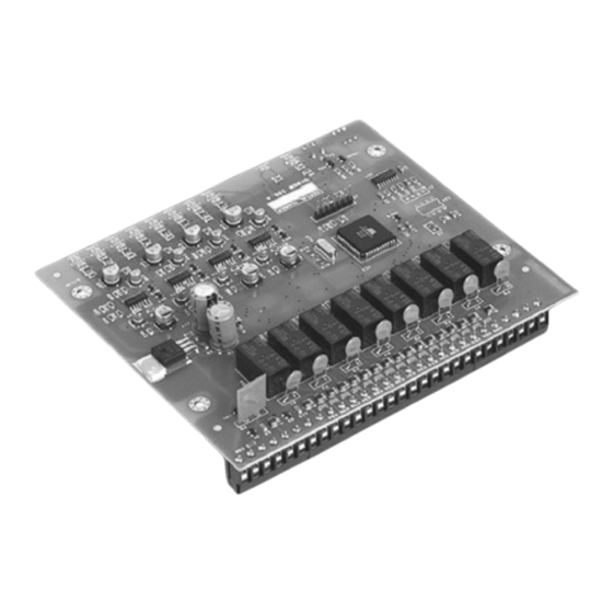
- Page 1 Sigma CP Sounder Board (K461) Operation and Maintenance Manual Man-1098 Issue 04 June 2013 https://www.acornfiresecurity.com/...
-
Page 2: Table Of Contents
https://www.acornfiresecurity.com/ Index Page 1. Introduction ....................3 2. Safety ......................3 3. Mounting ....................3 3.1 S461 PCB ........................3 3.2 K04000 and K04400 enclosures ..................4 4. Technical specification .................. 4 5. Connecting to the circuit board ..............5 6. -
Page 3: Introduction
https://www.acornfiresecurity.com/ 1. Introduction The Sigma CP Sounder board can to provide up to 8 additional sounder outputs from Sigma CP conventional fire panels via a 2 core data bus and an additional power supply. Sounder outputs are configurable as common, zonal or two stage alarm. The Sounder board is compatible with all Sigma CP control panels with software versions Sigma242.hex onwards. -
Page 4: K04000 And K04400 Enclosures
https://www.acornfiresecurity.com/ 3.2 K04000 and K04400 enclosures Suitable fixings should be used at all fixing points such that the enclosure is securely mounted and is not liable to move once fixed. The enclosure should not be mounted in another enclosure or near sources of excessive heat. Cables should be connected using suitable cable glands fitted to the knockouts provided. -
Page 5: Connecting To The Circuit Board
https://www.acornfiresecurity.com/ 5. Connecting to the circuit board All connections for field wiring are to rows of terminals along the top of the circuit board. Shielded fire alarm cable such as FP200 for power and RS485 data cable for comms and metal cable glands should be used for all connections to the board. -
Page 6: Input
https://www.acornfiresecurity.com/ 7. 24V Input Figure 1-Connection to sounder outputs The Sounder board requires a nominal 24V DC power supply to operate (21 to 30V). This power supply should be suitably rated to be able to supply sufficient power for the number of sounders that are connected to the sounder board. -
Page 7: Class Change Input
https://www.acornfiresecurity.com/ For each sounder board with maximum load (4A) the following battery capacity should be allowed. 24 hours – 3.6Ah 48 hours – 4.8Ah 72 hours – 5.8Ah 8. Class change input The sounder board has a “class change” input which operates all sounder outputs continuously while the input is activated and switches the sounder outputs off when the input is de-activated. - Page 8 https://www.acornfiresecurity.com/ Wiring can be standard fire alarm cable such as FP200 or shielded data cable. In either case, the shield of the cable must be securely bonded to the enclosure case at both ends. It is important to observe the polarity of the connections for correct operation. + should be connected to + and –...
-
Page 9: Initialising The Sounder Board
https://www.acornfiresecurity.com/ 10. Initialising the Sounder board After Sounder boards have been connected to the main panel, the main panel has to “learn” how many Sounder boards it has connected to it. This is necessary so that the main panel can announce a fault condition if one or more Sounder boards subsequently become disconnected. -
Page 10: Fuse Fail
https://www.acornfiresecurity.com/ 11.4 Fuse fail The Sounder board is fitted with a 4 Amp rated, self resetting electronic fuse. This fuse protects the electronics of the Sounder board and prevents any excessive loading of the power supply that is powering it. If this fuse operates, the yellow FUSE LED will light. 11.6 COMMS If the Sounder board loses communication with the control panel to which it is connected, the COMMS LED will light. -
Page 11: Overview
https://www.acornfiresecurity.com/ 12. Overview FIELD WIRING CONNECTS HERE BOARD MOUNTING HOLES CLASS RS485 RS485 PROCESSOR RESET ADDRESS ALARM COMMS FAULT FUSE SOUNDERS ACTIVATED LEDS OK LED SOUNDER ADDRESS SWITCH BITS 1 TO 3 FAULT LEDS COMMS FAIL LED ONLY ARE USED FUSE FAIL LED PROCESSOR RESET SWITCH Figure 6 –... - Page 12 https://www.acornfiresecurity.com/ 13. System wiring 2 CORE SERIAL DATA CABLE 2 CORE SERIAL DATA CABLE SIGMA CP CONTROL PANEL SOUNDER BOARD SOUNDER BOARD 3 CORE CABLE + 3 CORE CABLE + POWER FAULT SIGNAL POWER FAULT SIGNAL 24V BATTERY BACKED POWER SUPPLY Figure 7- System wiring Man-1098_SigmaCP_Sounder_Board_04...
Need help?
Do you have a question about the K461 and is the answer not in the manual?
Questions and answers