
Summary of Contents for GearLite CMA-9011-R
- Page 1 Ross Video Limited CMA-9011-R SDI Component Monitoring Amplifier with Reclocked SDI Outputs User Manual Ross Part Number: 9011RDR-004 Issue: 03C...
- Page 2 CMA-9011-R • SDI Component Monitoring Amplifier with Reclocked SDI Outputs User Manual • Ross Part Number: 9011RDR-004 • Document Issue: 03C • Printed in Canada. The information contained in this User Manual is subject to change without notice or obligation.
-
Page 3: Symbol Meanings
Important Regulatory and Safety Notices to Service Personnel Before using this product and any associated equipment, refer to the “Important Safety Instructions” listed below so as to avoid personnel injury and to prevent product damage. Products may require specific equipment, and /or installation procedures be carried out to satisfy certain regulatory compliance requirements. -
Page 4: Emc Notices
OR MOISTURE” Do not block ventilation openings. Install in accordance with manufacturer’s instructions. Do not install near heat sources such as radiators, heat registers, stoves, or other apparatus (including amplifiers) that produce heat. Do not use this apparatus near water. Only use attachments/accessories specified by the manufacturer. -
Page 5: Environmental Information
If the module does not appear to be working properly, please contact Technical Support using the numbers listed under the “Contact Us” section on the last page of this manual. All RossGear GearLite products are covered by a generous 3-year warranty and will be repaired without charge for materials or labor within this period. -
Page 7: Table Of Contents
DIP Switches ..............3-4 Status Indicator LED ............3-5 Specifications In This Chapter................4-1 Technical Specifications............ 4-1 Service Information In This Chapter................5-1 Warranty and Repair Policy ..........5-1 Ordering Information In This Chapter................6-1 Contents • i CMA-9011-R User Manual (Iss. 03C) - Page 8 • Contents CMA-9011-R User Manual (Iss. 03C)
-
Page 9: Introduction
DAC and special filtering techniques used in the design achieve a low-artifact video output. The front panel of the CMA-9011-R chassis provides a power status LED for visual reference. In addition, user-selectable settings are available to place the CMA-9011-R into the proper operating mode. Some of these modes are: monochrome output, 75% color bar pattern, and vertical interval blanking. -
Page 10: Functional Block Diagram
Functional Block Diagram Figure 1. Simplified Block Diagram of CMA-9011-R Functions Features The CMA-9011-R SDI Component Monitoring Amplifier with Reclocked SDI Outputs has the following features: • NTSC, PAL, or PAL-N operation • 10-bit DAC resolution • 8-bit data processing •... -
Page 11: Installation
Unpacking Unpack each CMA-9011-R module you received from the shipping container and check the contents against the packing list to ensure that all items are included. If any items are missing or damaged, contact your sales representative or Ross Video directly. - Page 12 BNC connectors. Velcro Strips The included Velcro strips allow the GearLite chassis and power supply to be affixed to a permanent location during use and easily removed for adjustments. Carefully consider the installation location before proceeding; the adhesive is very aggressive and is not easily removed.
- Page 13 4. To mount the power adaptor, apply the remaining mating Velcro strip set, repeating the previous steps. Installation • 2-3 CMA-9011-R User Manual (Iss. 03C)
- Page 14 Two pads can be used at the rear of the module to help support it when mounted in the GRF-9000 GearLite Rack Frame (see Optional Mounting Accessories). 2-4 • Installation...
-
Page 15: Optional Mounting Accessories
90° angle. Figure 4. BMP-9000 90° Mounting Bracket GRF-9000 The GRF-9000 GearLite Rack Frame is a rack mounting frame system for GearLite modules. The mounting system provides convenient organization for up to nine GearLite modules in only a 2RU space. - Page 16 The flat metal plate and small plastic label (see Figure 6) included with every GearLite module are used to mount a module into the GRF-9000. Complete instructions are included in the GRF-9000 User Manual. Figure 6. Flat Metal Plate and Label Positions for GRF-9000 Mounting 2-6 •...
-
Page 17: Setup And Operation
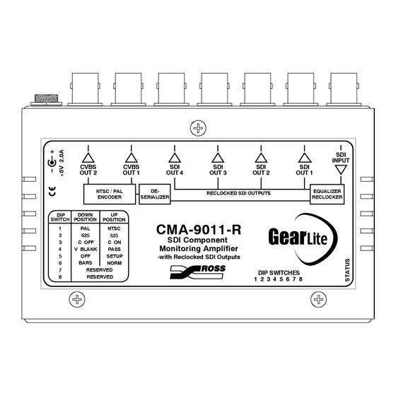
In This Chapter This section provides details of all operating modes and features. The following topics are discussed: • Cable Connections • User Controls • DIP Switches • Status Indicator LED Setup and Operation • 3-1 CMA-9011-R User Manual (Iss. 03C) - Page 18 Cable Connections Connect the cables to the CMA-9011-R according to the designations indicated on the chassis label. The input is internally terminated at 75 Ohms. It is not necessary to terminate unused outputs. Figure 7. CMA-9011-R Cable Connections Indicator Label Figure 8.
- Page 19 See the Important Regulatory and Safety Notices section at the beginning of this manual for details. User Controls The CMA-9011-R has the following front edge user controls: • DIP Switches • Status Indicator LED Figure 9. User Controls Setup and Operation •...
- Page 20 DIP Switches An 8-position DIP switch allows the user to configure the CMA-9011-R to fit into almost any installation. Settings are as described in the following table: Table 1. CMA-9011-R DIP Switch Menu Vertical Video Standard Chroma Setup Mode used...
- Page 21 Status Indicator LED The front edge of the module has an LED indicator to show the status of the amplifier. The module is operating correctly when the Status LED is lit. Table 2. CMA-9011-R LED Status Descriptions Display Status Description...
- Page 22 3-6 • Setup and Operation CMA-9011-R User Manual (Iss. 03C)
-
Page 23: Specifications
Specifications In This Chapter This chapter contains the Technical Specifications table. Technical Specifications Table 3. CMA-9011-R - Technical Specifications Category Parameter Specification Number of Inputs Signal Standards SMPTE 259M (conversion at Accommodated 270Mb/s only) Serial Digital Input Impedance 75Ω terminating... - Page 24 RMS Noise (unweighted) -53dB 0 - 5.0MHz Required Voltage +5 V DC (5% regulation) Power Current Consumption >425 mA typical Total Power >2.2 W typical Other Warranty 3-year transferable Specifications are subject to change without notification 4-2 • Specifications CMA-9011-R User Manual (Iss. 03C)
-
Page 25: Service Information
This chapter contains Warranty and Repair Policy information. Warranty and Repair Policy The RossGear CMA-9011-R is warranted to be free of any defect with respect to performance, quality, reliability, and workmanship for a period of THREE (3) years from the date of delivery to the customer. In the event that your... - Page 26 In Case of Problems Should any problem arise with your RossGear CMA-9011-R, please contact the Ross Video Technical Support Department. (Contact information is supplied at the end of this publication.) A Return Material Authorization number (RMA) will be issued to you, as well as specific shipping instructions, should you wish our factory to repair your RossGear CMA-9011-R.
-
Page 27: Ordering Information
2RU space) Your CMA-9011-R SDI Component Monitoring Amplifier with Reclocked SDI Outputs is part of the GearLite line of the RossGEAR family of products. Ross Video Limited offers a full line of RossGEAR digital terminal equipment including distribution, conversion, monitoring, synchronizers, encoders, decoders, amplifiers, keyers, switchers, as well as analog audio and video products. - Page 28 Contact Us Contact our friendly and professional support representatives for the following: • Name and address of your local dealer • Product information and pricing • Technical support • Upcoming trade show information General Business Office 613 • 652 • 4886 and Technical Support PHONE After Hours Emergency...
Need help?
Do you have a question about the CMA-9011-R and is the answer not in the manual?
Questions and answers