Table of Contents
Advertisement
Quick Links
Advertisement
Table of Contents

Related Manuals for Dedicated Micros Eco 9


Summary of Contents for Dedicated Micros Eco 9
- Page 1 Eco 9 Setup Guide...
- Page 2 Eco9 Dedicated Micros ©2006...
-
Page 3: Table Of Contents
Connecting External Devices ....................13 Confi guring the unit ........................16 Time, Date & Language ......................19 Camera Viewing .........................21 Schedule ............................22 Record Schedule ........................24 System Options .........................27 Record Options .........................32 Camera Setup ..........................35 Activity Camera Setup ......................36 Operator Reference ........................38 Dedicated Micros ©2006... -
Page 4: Introduction
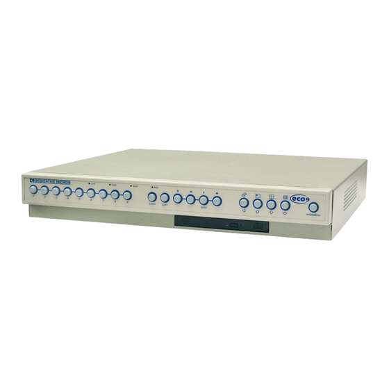
Eco9 ? 1.131 The Eco9 is part of the NetVu Connected range of DVR’s from Dedicated Micros, and is a cost effective and easy to use video multiplexer, digital video recorder, and network video transmitter in a single box solution. -
Page 5: Features
1. Installation –Giving details of how to install the unit and connect external devices. 2. Setup –Giving details of the confi guration menus of the unit. 3. Operating –Giving quick reference details on how to control the unit Dedicated Micros ©2006... -
Page 6: Important Safeguards
The user may fi nd the following booklet prepared by the Federal Communications Commission helpful: “How to Identify and Resolve Radio-TV Interference Problems”. This booklet is available from the US Government Printing Offi ce, Washington, DC20402, Stock No. 004-000-00345-4. Dedicated Micros ©2006... - Page 7 3.51 3.52 If this product is marked with the CE symbol it indicates compliance with all applicable directives. Directive 89/336/EEC. A ‘Declaration of Conformity’ is held at Dedicated Micros Ltd., 11 Oak Street, Swinton, Manchester M27 4FL. Laser 3.61 3.621 Some models of this unit have an integrated CD writer.
-
Page 8: Installing The Unit
However, other factors also determine the amount of time that can be stored on the disk of a digital multiplex recorder: The image quality The record rate The hard disk capacity 4.31 Dedicated Micros ©2006... -
Page 9: Image Quality
No. of cameras/Record rate 4.34 Calculating recording time The unit calculates the recording time automatically when the record rate and image quality are entered. Alternatively, an interactive record calculator is available for download from our web site: www.dedicatedmicros.com Dedicated Micros ©2006... -
Page 10: Simple Installation
9-way (Male) D-type RS-232 serial port (PPP modem) 485BUS MMJ port for DM/IR01 485-BUS Infrared receiver for use with SA- RC05 IR remote controller 5.153 Alarms and relays ALARMS 25-Way (Female) D-Type RELAYS 9-Way (Female) D-Type 5.204 Dedicated Micros ©2006... -
Page 11: Front Panel
The button under this symbol will show a four way split screen display on the Main (MON A) monitor. 5.2124 Multiscreen The button under this symbol will show a multiscreen display on the Main (MON A) monitor. 5.22 Dedicated Micros ©2006... -
Page 12: Vcr Buttons
5.24 LED’s 5.242 LIVE Unit is in Live mode when lit PLAY Unit is in Playback mode when lit SPOT Spot (MON B) monitor is being controlled RECORD Unit is recording video to the internal hard disk Dedicated Micros ©2006... -
Page 13: Quick Connection
Connect output marked MON B to the optional Spot monitor (analogue full-screen images). 5.33 STEP 3. Connect the External Devices If external devices need to be connected to the unit, go to the next section - ‘Connecting external devices’, before proceeding to Step 4. 5.341 Dedicated Micros ©2006... -
Page 14: Step 4. Connect Power
PSU to the rear of the unit and apply the power. The power-up procedure may take up to one minute. The unit will be ready to use once it this is complete. 5.35 The unit will now record all cameras in a 24-hour time-lapse mode without any further programming! 6.014 Dedicated Micros ©2006... -
Page 15: Connecting External Devices
The polarity of the alarms - normally open or normally closed - can be set in the ‘Camera Setup’ menu. Alarms Connection 1 - 9 Alarm Global Alarm 11 - 20 Reserved 21 - 25 Ground 6.5114 Dedicated Micros ©2006... - Page 16 “10.0.0.1”, the PPP IP address required to connect to the unit is “10.0.0.2”. The unit will request a username and password, as defi ned in the ‘profi les’ confi guration fi le. The default settings are ‘username’ and ‘password’. 6.73 Dedicated Micros ©2006...
- Page 17 fi le, and that this profi le has been confi gured in the email settings. Email settings are confi gured using the embedded web pages and the process is explained in the Networking guide.. Dedicated Micros ©2006...
-
Page 18: Confi Guring The Unit
Tapping the fwd or rew video keys will allow you to navigate back or forward one page in the menus. 9.04 To exit the menus Press and hold the Menu key to exit the menus. Tip: Tapping the Menu key until all the menus have been viewed will also exit. 9.05 Dedicated Micros ©2006... - Page 19 Time Date & Language Time & Date 15:38 24/Nov/2005 Date Format Day, Month Language English System Shutdown Disabled Timezone Greenwich Mean Time GMT +0 9.053 Use the button to change the settings, in this example 15:45. Dedicated Micros ©2006...
- Page 20 Navigation is also possible using the optional remote control instead of the cursor keys. 9.056 Warning: Images may be overwritten if the time or date is adjusted whilst recording is in progress. Tip: Ensure the timezone is correct before changing the time. 10.1 Dedicated Micros ©2006...
-
Page 21: Time, Date & Language
Note: Shutting down the unit by any other method will put the integrity of your DVR at risk. 10.161 Tip: The unit can be restarted from the ‘System Shutdown’ option by pressing and holding Camera 4. 10.17 Dedicated Micros ©2006... - Page 22 There are numerous time zones supported on the unit, select the zone for where the unit is installed so the time and date will refl ect the local time and will change in conjunction with Daylight Saving Time. 11.2 Dedicated Micros ©2006...
-
Page 23: Camera Viewing
Tip: It is advisable to set a password to stop this setting being altered by unauthorised personnel. 11.24 Note: The number of boxes displayed onscreen coresponds to the number of video inputs 12.301 Dedicated Micros ©2006... -
Page 24: Schedule
09:00 on Monday until it switches to the Night settings at 18:00. This is repeated each day until Friday when the settings will be switched to Day then over to Night settings on Saturday and back to Day on Sunday. 12.34 Dedicated Micros ©2006... - Page 25 The options are: • On between - this allows the start and end times to be set when theweekend settings will be applied. • Off - When the weekend option is off the weekend setting will never apply. 13.4001 Dedicated Micros ©2006...
-
Page 26: Record Schedule
When an event is triggered, if the Record rate is set to 1pps or above, the unit will switch to interleave record. The unit will interleave the event camera(s) with the non-event cameras and record at the specifi ed Event rate. 13.4202 Dedicated Micros ©2006... -
Page 27: Image Size
2KB to 30KB alongside the most appropriate image resolutions ensuring the optimum video quality is achieved. Tip: It is advised that the settings be tested to fi nd the best recorded video quality for the system being confi gured. Dedicated Micros ©2006... -
Page 28: Typical Settin Gs
‘Image Protection’ menu before it can be used for recording again. 13.49 Earliest unprotected recording The earliest unprotected recording displays the date and time of the fi rst image on the disk that has not been protected. 20.01 Dedicated Micros ©2006... -
Page 29: System Options
20.305 Network Network S S ettin etting g s s System name DHCP Enabled Disabled TCP/IP 000.000.000.000 Subnet mask 255.255.000.000 Default gateway 000.000.000.000 Bandwidth selection Edit PPP selection Edit Secondary web server port 8324 20.306 Dedicated Micros ©2006... - Page 30 Custom - this will allow the Administrator to select specifi c values. • ISDN - This will set the maximum transmission rate to 64KBits/second for remote network connection via an ISDN link, it will also automatically alter the transmit image buffers and Ethernet re-transmit timeout. Dedicated Micros ©2006...
-
Page 31: Ethernet Mtu
MTU sizes can vary for each connection and it may be necessary to use trial and error to fi nd the optimal MTU. Suggested MTU sizes are as follows; Dedicated Micros recommend you obtain this information from your Internet Service Provider who will provide you with the optimal fi gure. - Page 32 For a dial-out connection this is the password the unit will provide to authenticate with the remote computer. <Port> • This defi nes the PPP port over which the connection is made. For a PPP connection via Serial 1 on the unit this is “PPP_Link2”. Dedicated Micros ©2006...
-
Page 33: Factory Default
IP address. 20.325 Factory Default This will switch the majority of the settings back to factory default. However hardware specifi c settings such as the IP address will remain unchanged. Dedicated Micros ©2006... -
Page 34: Record Options
This is the amount of time the images are protected after the Global alarm has ended. By default this setting is 15 minutes, but this is adjustable from 00 minutes (no post-alarm protection) to 60 minutes 21.024 Image Protection Selecting this option allows images to be protected or unprotected manually. 21.025 Dedicated Micros ©2006... - Page 35 Protected images reduce the amount of space you have for normal recording. For example, if 50% of the images are protected, this effectively means you only have half the disk available for normal recording, so recording settings that should normally give you 30 days would only allow 15 days of recording. 21.3 Dedicated Micros ©2006...
-
Page 36: Event Database
This read only setting identifi es the existing number of entries within the event database. 21.34 Maximum Number of Entries This sets the maximum entries within the event database. Changing this will reset the event database and clear all previously stored events. Dedicated Micros ©2006... -
Page 37: Camera Setup
If the video input is not to be monitored for camera failure select Connected - Ignore cam fail. Tip: This menu can be entered directly by pressing and holding a camera button. Dedicated Micros ©2006... -
Page 38: Activity Camera Setup
A 16 x 16 grid can mask areas where activity detection is enabled. Select ‘Setup’ and follow the on- screen menus to confi gure the activity grid. Note: An NTSC video source will display an activity grid of 16 x 14. 24.1 Dedicated Micros ©2006... - Page 39 Use this option to test and tune the sensitivity and activity grid set up for each camera. When activity is detected on the camera a yellow box is displayed. Press the MODE/MENU button to exit the test. Dedicated Micros ©2006...
-
Page 40: Operator Reference
To enter this option, with the Event Log displayed press the EVENT button again. This will display the Event Search Filter menu. Tip: You can enter this menu by pressing and holding the EVENT button. 31.08 Dedicated Micros ©2006... -
Page 41: Zooming An Image
Press the Multiscreen button to toggle between a 9-way, 6-Way, 4+3 or 8+2 display. Press and hold the Multiscreen button to edit the display, use to select the segment, press the required camera button to fi ll that segment. Press MODE/MENU to exit. 31.14 Dedicated Micros ©2006... -
Page 42: Sequencing Cameras
‘Network Settings’ menu, described later in the manual. Note: If a password has been confi gured it will be necessary to enter the Username and Password information to gain access to the unit. The default user name and password are dm and web. 31.154 Dedicated Micros ©2006... - Page 43 Although the CDR drive may have a DVD-ROM label on the drawer it is not possible to read or write to DVD media. To insert a CDR: 31.1572 Press the button on the CDR drawer Pull the CD drawer out until there is resistance Dedicated Micros ©2006...
-
Page 44: Event Type
• All - this will select all of the above options and fi nd all associated recordings. 31.1588 Filter from Enter the time and date you wish to search from. The default is the earliest recorded time of the disk. 31.1589 Filter to Enter the end time and date for the search. 31.159 Dedicated Micros ©2006... -
Page 45: Play An Event Back Full Screen
Start a new search If you wish to start a new search fi lter, tap the Event key to exit the Event Log, then re-enter data in the Event Search Filter menu as described in step 1. 31.161 Dedicated Micros ©2006... - Page 46 This will start the archive process to the CD. Archive& Verify If you want to verify archiving has been successful, select this option instead. 31.164 To select any of the above options, highlight the option and tap MODE/MENU . To add images to the CD: Dedicated Micros ©2006...
- Page 47 Press the COPY key, a message will be displayed to say the event has been copied. Confi rm the fi les have been added to the archive list by selecting the Disk Archive List menu. Dedicated Micros ©2006...
- Page 48 Tel: +49 2433 5258-0 Tel: +1 310 791-8666 Fax: +49 2433 5258-10 Fax: +1 310 791-9877 Dedicated Micros France Dedicated Micros, Australia PTY. 9-13 rue du Moulinet 5/3 Packard Avenue, Castle Hill, 75013 Paris, France NSW 2154, Australia Tel : +33 (0) 1 45 81 99 99...
Need help?
Do you have a question about the Eco 9 and is the answer not in the manual?
Questions and answers