Table of Contents
Advertisement
Quick Links
User Manual of Product 1:
FLIR C3-X Compact Thermal Camera, Inspection Tool for
Electrical/Mechanical, Building, and Maintenance Applications,
with WiFi
User Manual of Product 2:
Klein Tools ET120 Gas Leak Detector, Combustible Gas Leak
Tester with 18-Inch Gooseneck Has Range 50 - 10,000 ppm,
Includes Pouch, Batteries
Advertisement
Table of Contents

Related Manuals for Klein Tools ET120


Summary of Contents for Klein Tools ET120
- Page 1 FLIR C3-X Compact Thermal Camera, Inspection Tool for Electrical/Mechanical, Building, and Maintenance Applications, with WiFi User Manual of Product 2: Klein Tools ET120 Gas Leak Detector, Combustible Gas Leak Tester with 18-Inch Gooseneck Has Range 50 - 10,000 ppm, Includes Pouch, Batteries...
- Page 2 User’s manual FLIR Cx series...
- Page 3 Important note Before operating the device, you must read, understand, and follow all instructions, warnings, cautions, and legal disclaimers. Důležitá poznámka Před použitím zařízení si přečtěte veškeré pokyny, upozornění, varování a vyvázání se ze záruky, ujistěte se, že jim rozumíte, a řiďte se jimi.
-
Page 4: Table Of Contents
Table of contents Disclaimers ..................1 Legal disclaimer ............... 1 U.S. Government Regulations............1 Patents ................... 1 Quality assurance ..............1 Third-party licenses..............1 Usage statistics ................ 1 Copyright ................1 Safety information ................2 Accessing regulatory information..........3 Notice to user ...................4 Calibration................ - Page 5 Table of contents About image files ..............17 9.2.1 File-naming convention ..........17 Adding a note ................ 17 Editing a saved image.............. 17 Uploading images ................19 10.1 Connecting to Wi-Fi..............19 10.2 Pairing with FLIR Ignite............. 19 10.3 Automatic upload..............19 10.4 Manual upload ...............
- Page 6 Table of contents 17.3 Supporting our customers............36 #T810539; r. AD/68933/69002; en-US...
-
Page 7: Disclaimers
Disclaimers 1.1 Legal disclaimer For warranty terms, refer to https://www.flir.com/warranty. 1.2 U.S. Government Regulations This product may be subject to U.S. Export Regulations. Send any inquiries to export- questions@flir.com. 1.3 Patents This product is protected by patents, design patents, patents pending, or design patents pending. -
Page 8: Safety Information
Safety information WARNING Applicability: Class B digital devices. This equipment has been tested and found to comply with the limits for a Class B digital device, pur- suant to Part 15 of the FCC Rules. These limits are designed to provide reasonable protection against harmful interference in a residential installation. -
Page 9: Accessing Regulatory Information
Safety information CAUTION Do not use the camera in temperatures more than +50°C (+122°F), unless other information is specified in the user documentation or technical data. High temperatures can cause damage to the camera. CAUTION Do not attach the batteries directly to a car’s cigarette lighter socket, unless FLIR Systems supplies a specific adapter to connect the batteries to a cigarette lighter socket. -
Page 10: Notice To User
Notice to user 3.1 Calibration We recommend that you send in the camera for calibration once a year. Contact your lo- cal sales office for instructions on where to send the camera. 3.2 Accuracy For very accurate results, we recommend that you wait 5 minutes after you have started the camera before measuring a temperature. -
Page 11: Note About Authoritative Versions
Notice to user 3.7 Note about authoritative versions The authoritative version of this publication is English. In the event of divergences due to translation errors, the English text has precedence. Any late changes are first implemented in English. #T810539; r. AD/68933/69002; en-US... -
Page 12: Customer Help
Customer help 4.1 General For customer help, visit: http://support.flir.com 4.2 Submitting a question To submit a question to the customer help team, you must be a registered user. It only takes a few minutes to register online. If you only want to search the knowledgebase for existing questions and answers, you do not need to be a registered user. -
Page 13: Quick Start Guide
Quick start guide 1. Push the On/off button to turn on the camera. 2. Follow the instructions on the camera screen to select the language, units, date and time formats, etc. 3. You can easily set up the camera to upload images for storage online. To enable upload of images, you need to connect your camera to a FLIR Ignite ac- count. -
Page 14: Camera Overview
Camera overview 6.1 View from the front 1. Camera lamp. 2. Infrared lens. 3. Visual camera lens. 4. Lanyard attachment point. 6.2 View from the rear 5. USB-C connector. 6. Camera screen. 7. On/off button. 8. Save button. 9. Tripod mount. #T810539;... -
Page 15: Screen Elements
Camera overview 6.3 Screen elements 6.3.1 General 1. Result table. 2. Status icons. 3. Live view button. 4. Gallery button. 5. Settings button. 6. Menu button. 7. Spotmeter. 8. Temperature scale. 6.3.2 Menu system To display the menu system, tap the menu button 1. -
Page 16: Swipe-Down Menu
Camera overview 6.3.4 Swipe-down menu To open the swipe-down menu, place your finger at the top of the screen and swipe down. 1. Battery status indicator. 2. Control buttons: • Wi-Fi button: Tap to enable/disable Wi-Fi. See also section 10.1 Connecting to Wi-Fi, page 19. -
Page 17: Achieving A Good Thermal Image
Achieving a good thermal image These are the functions and settings you need to experiment with to achieve a good ther- mal image: • Adjusting the temperature scale. • Selecting a suitable temperature range. • Selecting a suitable image mode. •... -
Page 18: Example 2
Achieving a good thermal image 7.2.2 Example 2 Here are two infrared images of an isolator in a power line. To make it easier to analyze the temperature variations in the isolator, the temperature scale in the right image has been changed to values close to the temperature of the isolator. -
Page 19: Temperature Range
Achieving a good thermal image 1. Tap the Settings button 2. Tap Device settings > Show temperature scale. 3. Show/hide the temperature scale by toggling the Show temperature scale switch. 7.3 Temperature range The camera is calibrated for different temperature ranges. For accurate temperature measurements, you must change the Camera temperature range setting to suit the ex- pected temperature of the object you are inspecting. -
Page 20: Color Palettes
Achieving a good thermal image To align the thermal and visual images, do the following: 1. Tap the screen. This displays a box with a distance in the upper right corner. 2. Tap the distance box. This displays a slider. 3. -
Page 21: Measuring Temperatures
Measuring temperatures You can measure a temperature using a spotmeter or a box. The measured tempera- tures are displayed in the result table on the screen. • With a spotmeter, the camera measures the temperature at the position of the spotmeter. -
Page 22: Changing The Measurement Parameters
Measuring temperatures 8.4 Changing the measurement parameters For accurate temperature measurements, it is important to use appropriate measure- ment parameters: • Emissivity: The emissivity determines how much of the radiation originates from the object as opposed to being reflected by it. •... -
Page 23: Saving And Working With Images
Saving and working with images 9.1 Saving an image To save an image, push the Save button at the top of the camera. When you save an image, the camera stores the image file in the camera memory. You can also set up the camera to upload images for storage online, see section 10 Upload- ing images, page 19. - Page 24 Saving and working with images 4. Manual adjustment mode is now active. For adjustment instructions, see section 7.2.3 Manually adjusting the temperature scale, page 12. 5. Tap the menu button • To change the image mode, tap Image mode • To add a measurement tool, tap Measurement •...
-
Page 25: Uploading Images
Uploading images You can set up the camera to upload images for storage online. To enable upload of images, you need to connect the camera to a Wi-Fi network and pair the camera with a FLIR Ignite account. If automatic upload is enabled, new images will automatically be uploaded to your FLIR Ignite account when the camera is connected to a Wi-Fi network. -
Page 26: Uploading Multiple Images
Uploading images 3. Tap a folder and then tap an image. 4. Tap and then tap Upload. 10.4.2 Uploading multiple images 1. Make sure the camera is connected to a Wi-Fi network. 2. Tap the Gallery button 3. Tap a folder. 4. -
Page 27: Working With The Image Gallery
Working with the image gallery When you save an image, the camera stores the image file in the image gallery of the camera. You can open an image in the image gallery and, for example, change the color palette, apply another image mode, and add measurement tools. The image gallery can include one or several folders. -
Page 28: Changing The Active Folder
Working with the image gallery 11.4 Changing the active folder New images are saved to the active folder. To change the active folder, do the following: 1. Tap the Gallery button 2. Tap the folder that new images should be saved to. 3. - Page 29 Working with the image gallery To delete all images, do the following: 1. Tap the Settings button 2. Tap Save options & storage and then tap Delete all saved files..This displays a dia- log box. 3. To permanently delete all images, tap Delete. #T810539;...
-
Page 30: Handling The Camera
Handling the camera 12.1 Charging the battery You can charge the battery by using a standard USB power adapter or by connecting the camera to a computer. It is good practice to disconnect the camera from power when the battery is fully charged. The battery status is displayed on the swipe-down menu, see section 6.3.4 Swipe-down menu, page 10. -
Page 31: Non-Uniformity Correction
Handling the camera 1. Tap the Settings button 2. Tap Connections > Bluetooth. 3. Make sure Bluetooth is enabled by toggling the Bluetooth switch. Note On the mobile phone, you must also make sure that Bluetooth is enabled, that the phone is in discovery mode, and that Bluetooth tethering is enabled. 4. - Page 32 Handling the camera 12.7.2.2 Equipment Cotton wool CAUTION If you use a lens cleaning cloth it must be dry. Do not use a lens cleaning cloth with the liquids that are given in section 12.7.2.1 above. These liquids can cause material on the lens cleaning cloth to become loose.
-
Page 33: Camera Settings
Camera settings The Settings menu includes the following: • Measurement parameters. • Connections. • Camera temperature range. • Save options & storage. • Accounts. • Device settings. To display the Settings menu, tap the Settings button 13.1 Measurement parameters For accurate temperature measurements, it is important to use appropriate measure- ment parameters. -
Page 34: Device Settings
Camera settings When the camera is paired, the Accounts dialog box displays the following information: • The FLIR Ignite account that the camera is paired with. • The link to FLIR Ignite: https://ignite.flir.com • The current storage capacity in your FLIR Ignite account. 13.6 Device settings •... -
Page 35: Updating The Camera
Updating the camera To take advantage of our latest camera firmware, it is important that you keep your cam- era updated. When the camera is connected to the internet, you can check for updates and install new firmware versions online. You can also update the camera by connecting the camera to a computer using the USB cable. -
Page 36: Mechanical Drawings
Mechanical drawings [See next page] #T810539; r. AD/68933/69002; en-US... -
Page 38: Ce Declaration Of Conformity
CE Declaration of conformity [See next page] #T810539; r. AD/68933/69002; en-US... - Page 39 May 5, 2020 Täby, Sweden AQ320383 CE Declaration of Conformity – EU Declaration of Conformity Product: FLIR C5-series Name and address of the manufacturer: FLIR Systems AB PO Box 7376 SE-187 15 Täby, Sweden This declaration of conformity is issued under the sole responsibility of the manufacturer. The object of the declaration: FLIR C5 -series (Product Model Name FLIR-C8940).
-
Page 40: About Flir Systems
About FLIR Systems FLIR Systems was established in 1978 to pioneer the development of high-performance infrared imaging systems, and is the world leader in the design, manufacture, and mar- keting of thermal imaging systems for a wide variety of commercial, industrial, and gov- ernment applications. -
Page 41: More Than Just An Infrared Camera
About FLIR Systems France, Germany, Great Britain, Hong Kong, Italy, Japan, Korea, Sweden, and the USA —together with a worldwide network of agents and distributors—support our internation- al customer base. FLIR Systems is at the forefront of innovation in the infrared camera industry. We antici- pate market demand by constantly improving our existing cameras and developing new ones. -
Page 42: Supporting Our Customers
About FLIR Systems The staff of the ITC are also there to provide you with any application support you may need in putting infrared theory into practice. 17.3 Supporting our customers FLIR Systems operates a worldwide service network to keep your camera running at all times. - Page 43 last page Website http://www.flir.com Customer support http://support.flir.com Copyright © 2020, FLIR Systems, Inc. All rights reserved worldwide. Disclaimer Specifications subject to change without further notice. Models and accessories subject to regional market considerations. License procedures may apply. Products described herein may be subject to US Export Regulations. Please refer to exportquestions@flir.com with any questions. Publ.
- Page 44 ET120 ENGLISH INSTRUCTION MANUAL Combustible Gas Leak Detector • DETECTS A RANGE OF COMBUSTIBLE GASSES • AUDIBLE AND VISUAL ALARMS • DATA HOLD ESPAÑOL pg. 7 FRANÇAIS pg. 13...
-
Page 45: General Specifications
ENGLISH GENERAL SPECIFICATIONS Klein Tools ET120 is an easy-to-use tester that provides audible and visual alarms in the presence of methane, propane and butane at concentrations as low as 50 ppm. • Audible Alert: 85 db ticking, modulation proportional to gas concentration •... -
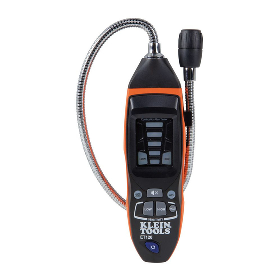
Page 46: Feature Details
FEATURE DETAILS Front of Back of Tester Tester Gooseneck Auto Power-Off Button Gooseneck Clip LOW Sensitivity Mode Button Sensor Head HIGH Sensitivity Mode Button Indicator Lights HOLD Button LOW Alert Light Power Button HIGH Alert Light 1/4-20 UNC Tripod Mount Auto-Zero Button Battery Door Mute Button... -
Page 47: Function Buttons
ENGLISH SYMBOLS ON METER Warning Wear approved eye protection Risk of Read instructions Electric Shock Not intended for use as Personal Explosive Materials Protective Equipment (PPE) Do NOT probe moving machinery FUNCTION BUTTONS AUTO-ZERO BUTTON Press to set zero point in a known clean environment. MUTE BUTTON Press to mute the audible alarm. - Page 48 OPERATING INSTRUCTIONS 1. In an area where combustible gas is known to be not present, press the power button for 3 seconds. The tester will beep and start a 50-second zero-calibration process while the first indicator light blinks . Once complete, all indicator lights will blink for one second, then the HIGH indicator light will illuminate and...
-
Page 49: Maintenance
SENSOR SERVICING When ALL lights on the tester are illuminated, the sensor has failed and the unit must be serviced. Contact Klein Tools at 1-877-775-5346 or customerservice@kleintools.com for further details. There are no user-serviceable parts inside tester. CLEANING Be sure tester is turned off and wipe with a clean, dry lint-free cloth. - Page 50 ET120 ESPAÑOL MANUAL DE INSTRUCCIONES Detector de fuga de gas combustible • DETECTA UNA VARIEDAD DE GASES COMBUSTIBLES • ALARMAS AUDIBLES Y VISUALES • RETENCIÓN DE DATOS...
-
Page 51: Especificaciones Generales
ESPAÑOL ESPECIFICACIONES GENERALES El ET120 de Klein Tools es un medidor fácil de utilizar que emite alarmas audibles y visuales ante la presencia de metano, propano y butano en concentraciones tan bajas como 50 ppm. • Alarma audible: tictac de 85 dB, con modulación proporcional a la concentración de gas... - Page 52 DETALLES DE LAS CARACTERÍSTICAS Parte posterior Parte frontal del probador del probador 1. Cuello de cisne 10. Botón LOW Sensitivity 2. Sujetador del cuello de cisne (Modo de sensibilidad baja) 3. Cabeza del sensor 11. Botón HIGH Sensitivity 4. Luces indicadoras (Modo de sensibilidad alta) 5.
-
Page 53: Botones De Funciones
ESPAÑOL SÍMBOLOS DEL MEDIDOR Advertencia Use protección para ojos aprobada. Riesgo de Lea las instrucciones. choque eléctrico. No diseñado para usarlo Material explosivo. como equipo de protección personal (PPE). NO utilizar la sonda en máquinas en movimiento. BOTONES DE FUNCIONES BOTÓN AUTO-ZERO (CALIBRACIÓN AUTOMÁTICA DEL CERO) Presione este botón para establecer el punto cero en un ambiente puro conocido. -
Page 54: Instrucciones De Operación
INSTRUCCIONES DE OPERACIÓN 1. En áreas donde se sabe que hay presencia de gas combustible, mantenga presionado el botón de encendido durante 3 segundos. El probador emitirá un pitido e iniciará un proceso de calibración del cero que durará 50 segundos, mientras la primera luz indicadora se enciende de forma intermitente. -
Page 55: Mantenimiento
Cuando TODAS las luces del probador 4 , 5 , 6 , 7 y 8 se encienden, el sensor 3 tiene una falla y es necesario reparar la unidad. Comuníquese con Klein Tools al 1-877-775-5346 o escriba a customerservice@kleintools.com para obtener más detalles. El probador no contiene en su interior piezas que el usuario pueda reparar. -
Page 56: Manuel D'utilisation
ET120 FRANÇAIS MANUEL D’UTILISATION Détecteur de fuite de gaz combustible • DÉTECTE PLUSIEURS GAZ COMBUSTIBLES • ALARMES SONORES ET VISUELLES • MAINTIEN DES DONNÉES... -
Page 57: Caractéristiques Générales
FRANÇAIS CARACTÉRISTIQUES GÉNÉRALES Le détecteur ET120 de Klein Tools est un testeur facile à utiliser qui déclenche des alarmes sonores et visuelles en présence de méthane, de propane et de butane à des concentrations aussi faibles que 50 ppm. • Alerte sonore : son de clic de 85 dB dont la modulation est proportionnelle à... -
Page 58: Caractéristiques Détaillées
CARACTÉRISTIQUES DÉTAILLÉES Avant du Arrière du testeur testeur 1. Col de cygne 9. Bouton APO (arrêt automatique) 2. Pince pour le col de cygne 10. Mode de sensibilité LOW (faible) 3. Tête du capteur 11. Mode de sensibilité HIGH (élevée) 4. -
Page 59: Boutons De Fonction
FRANÇAIS SYMBOLES SUR LE DÉTECTEUR Porter une protection Avertissement oculaire approuvée Risque de Lire les instructions choc électrique Ne fait pas office d’EPI Matières explosives Ne PAS utiliser sur des pièces en mouvement BOUTONS DE FONCTION BOUTON AUTO ZERO (ÉTALONNAGE AUTOMATIQUE DU ZÉRO) Appuyez sur ce bouton pour configurer le point de référence zéro dans un environnement que vous savez exempt de gaz combustibles. -
Page 60: Instructions D'utilisation
INSTRUCTIONS D’UTILISATION 1. Dans une zone que vous savez exempte de gaz combustibles, appuyez sur le bouton de mise sous tension et maintenez- le enfoncé pendant 3 secondes. Le testeur émettra un signal sonore et lancera un processus d’étalonnage du zéro sur 50 secondes. -
Page 61: Entretien
FRANÇAIS ENTRETIEN REMPLACEMENT DES PILES Lorsque les témoins d’alerte LOW (faible) 5 et HIGH (élevée) 6 sont allumés en même temps, cela signifie que les piles doivent être remplacées. AVERTISSEMENT : Ne remplacez PAS les piles du détecteur dans une atmosphère explosive. 1. - Page 62 NOTES / NOTAS / REMARQUES...
- Page 63 NOTES / NOTAS / REMARQUES KLEIN TOOLS, INC. 450 Bond Street Lincolnshire, IL 60069 1-877-775-5346 customerservice@kleintools.com www.kleintools.com 1390185 Rev 06/17 B...
Need help?
Do you have a question about the ET120 and is the answer not in the manual?
Questions and answers