
Summary of Contents for MARINE DATA MD77ROT
- Page 1 …navigation with innovation USER MANUAL MD77ROT F077201 - RATE OF TURN INDICATOR (ANALOGUE) MD77ROT-MA-v04r07 2015-03-27 ENGLISH...
-
Page 3: Table Of Contents
MD77ROT CONTENTS MD77ROT RATE OF TURN INDICATOR (ANALOGUE) ..... 5 DOCUMENT ..................6 About This Manual ..................6 NOTICE ....................7 Copyright ...................... 7 DESCRIPTION ..................8 PRINCIPLE OF OPERATION .............. 9 APPLICATION ..................9 SPECIAL FEATURES ............... 10 MAJOR DIMENSIONS ..............11 INSTALLATION ................. - Page 4 12.2 Fault-Finding ....................21 12.2.1 MD77ROT does not operate ............21 12.2.2 MD77ROT aligns to 0 but does not follow the source data ..... 21 12.2.3 Display illumination not functioning ..........21 12.2.4 Display illumination flashing or Alarm indications present ....21 12.2.5 Automatic warning of loss of valid Rate of Turn Data ......
-
Page 5: Md77Rot Rate Of Turn Indicator (Analogue)
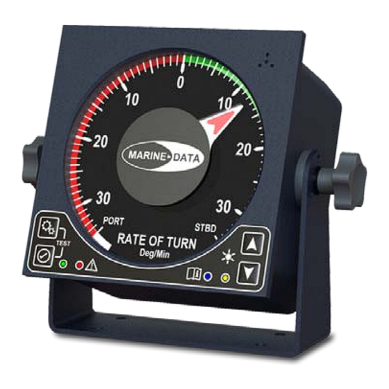
MD77ROT 1 MD77ROT RATE OF TURN INDICATOR (ANALOGUE) Bulkhead Bracket Mounted (Option) Rear View Panel Mounted (Standard) -
Page 6: Document
About This Manual This Manual provides installation, operating Instructions and fault-finding procedures for the MARINE DATA MD77ROT Rate of Turn Indicator (Analogue). After installation, this manual should remain with the vessel to which it relates. This manual may also be made available in electronic Portable Document Format (PDF). -
Page 7: Notice
Vittlefields Technology Centre Forest Road NEWPORT Isle of Wight PO30 4LY UNITED KINGDOM tel: +44 (0)1983 822180 email: info@marine-data.co.uk fax +44(0)1983 822181 web: www.marine-data.co.uk MARINE DATA SYSTEMS LIMITED reserves the right to make changes to its products and specifications without notice... -
Page 8: Description
MD77ROT 4 DESCRIPTION The MARINE DATA MD77ROT Rate of Turn Indicator is a NMEA 0183 based indicator which displays the ship’s Rate of Turn in degrees per minute. It has an operating range of 0 to 35 degrees per minute rate of turn to either Port or Starboard. It is equipped with an analogue display scale graduated in 1 degree increments. -
Page 9: Principle Of Operation
MD77ROT 5 PRINCIPLE OF OPERATION The MD77ROT accepts data in digital RS422 format using a conventional NMEA 0183 (IEC 61162-1) Rate of Turn sentence. The input is processed by electronic circuitry contained within the Indicator enclosure. On application of power and a correct transmission signal to the Indicator, an embedded micro-controller processes the received heading information and in turn drives a stepper-motor connected to the pointer. -
Page 10: Special Features
Supply under-voltage warning Optional Remote Alarm / Acknowledge facility The MD77ROT has a Remote Dimmer feature. With this feature, the illumination level may be adjusted via an external dimmer signal. The remote dimmer operates on a standard 0-24V DC signal (with reference to power supply negative). This signal can be used to implement a... -
Page 11: Major Dimensions
MD77ROT 8 MAJOR DIMENSIONS All dimensions mm Panel and Bulkhead mounting options shown:... -
Page 12: Installation
Connect the MD77ROT in accordance with table 9.3 - Pin Connections (by function). The MD77ROT is designed to use 24V DC and accept a digital RS422 data signal using the NMEA 0183 protocol. Ensure all incoming supply and signal cables are either suitably insulated and/or connected, or bonded to the vessel’s earth where appropiate. -
Page 13: Pin Connections (By Function)
CAUTION: APPLICATION OF ANY VOLTAGE OTHER THAN THOSE STIPULATED IN THIS PRODUCT SPECIFICATION MAY DAMAGE THE INDICATOR The MD77ROT is supplied with 2.5M data cable, it is recommended that this is connected to the ships data and power cable/s within a Junction Box, Marine data can supply an 8-way Junction Box suitable for this purpose at either IP54 (MD69CB) for internal use or IP65 (MD69CBW) for external use. -
Page 14: Pin Identification
MD77ROT Pin Identification Pin Idents of the 15-pin fixed D-type socket connector (view looking on the rear panel of the MD77ROT):... -
Page 15: Wiring Diagram
MD77ROT Wiring Diagram... -
Page 16: Commissioning The System
Apply system power (24V DC) to the MD77ROT. The MD77ROT Indicator will initially align to 0 degrees per minute; it will then adopt the transmitted angle sent by the signal source. If no signal is present, it will display a No Signal error indication;... -
Page 17: Operation
MD77ROT 11 OPERATION 11.1 Operator Controls Function Button - SETTINGS and ADJUST DAMPING Function Button - TEST, CLEAR DAMPING and RE ALIGN in conjuction with SETTINGS button C Green LED - NORMAL Indicator (5Hz flash in TEST mode) D Red LED - ALARM / FAULT Indicator... -
Page 18: Illumination
MD77ROT 11.2 Illumination The Illumination Level of the Scale, Pointer and Indicators for the MD77ROT is adjusted using the UP and DOWN buttons. There are 40 levels of brightness from OFF to MAXIMUM. Pressing the UP button will increase the illumination level by one step; holding the button will slowly increase the illumination to MAXIMUM. -
Page 19: Settings: Adjust Damping
Flashing 5Hz 10 seconds Damping is adjusted with the ADJUST DAMPING function, accessible via the Function buttons on the MD77ROT. Each change of damping setting using the ADJUST DAMPING function is accompanied by an audible tone. Increasing the Damping Setting is performed by pressing both the SETTINGS the UP buttons together and holding for 1 second. -
Page 20: Alarm: Low Power Supply
11.6 Automatic Baud Rate Detection If valid data is not received and a No Data error is active, then the MD77ROT will scan all available Baud rates to obtain valid data at an alternative baud rate. If valid data is discovered which corresponding to the list of acceptable data sentences then the new Baud rate will be stored and used for future data reception. -
Page 21: Maintenance And Fault-Finding
No scheduled maintenance is required. It is recommended to gently wipe away any accumulated dust periodically with a soft lint free cloth. Note: The MD77ROT is a sealed unit and has no user-serviceable parts inside. Breaking the factory seal will invalidate the warranty. -
Page 22: Automatic Detection Of Previously Lost Rate Of Turn Data
12.2.7 Automatic detection of absent Rate of Turn data on Power-Up If the Rate of Turn data is absent on power-up the MD77ROT will automatically detect this. The pointer assumes a vertical downward position and the Red warning LED will... -
Page 23: Technical Support
MD77ROT 12.3 Technical Support If further technical support is required then please contact your local MARINE DATA agent or MARINE DATA Technical Support: • By email: support@marine-data.co.uk • Through our website: www.marine-data.co.uk All technical support enquiries must include the following basic equipment information: About your MARINE DATA Equipment: MARINE DATA Equipment Model number (e.g. -
Page 24: Specifications
MD77ROT 13 SPECIFICATIONS 13.1 Physical Weight: 1.25kg (with bulkhead mounting bracket) Bulkhead mounted: Width 200mm; Height 166mm; Dimensions: Depth 87mm (excluding data cable) Fascia Dimensions: 144mm x 144mm x 6mm Deep Mounting: Panel-mounted or optional Bulkhead mounting bracket 1x 15-way D-type connector; M4 Earth stud Connections: (supplied with 2.5M data cable) -
Page 25: Environmental
) on request Supplied with 2.5m of data cable terminated with a 15-pin D-sub type connector The MD77ROT is only to be used with a Type Approved Rate of Turn Sensor in accordance with IMO Resolution A.526 (13) If spare parts are required then please contact either your supplier or MARINE DATA. -
Page 26: Grounding And Shielding
MD77ROT 14 GROUNDING AND SHIELDING This indicator is designed to be grounded via an M4 earth stud provided on the rear panel. This earth stud provides the electrical contact for protective earth bonding. The power/data connector has a conductive outer casing which, when mated, connects to the unit enclosure. -
Page 27: Safety And Security
MD77ROT 15 SAFETY AND SECURITY Please observe the following procedures to ensure safety of personnel installing and operating the equipment: • Ensure all power to the unit is disconnected and locked-out during installation, maintenance and removal procedures • Ensure power is disconnected and locked-out in the event of mechanical damage to the unit, rendering internal parts accessible to personnel •... -
Page 28: Glossary Of Terms
MD77ROT 16 GLOSSARY OF TERMS Term Description Electro-Magnetically Compatibility - specifically measured against MIL-SPEC-461 Electromagnetic Compass (fluxgate coil compass) Maritime navigation and radio communication equipment and systems. EN60945 General requirements. Methods of testing and required test results. Ingress Protection Rating... -
Page 29: About Marine Data
In the cruise liner industry, MARINE DATA is the choice again; you will find our equipment on the liners of the world’s leading leisure operators - including P&O™ and Disney®. In the fishing industry, MARINE DATA is there to help the world’s fishing skippers harvest the... - Page 30 MD77ROT NOTES...
- Page 31 MD77ROT NOTES...
- Page 32 MARINE DATA SYSTEMS LIMITED Vittlefields Technology Centre Forest Road NEWPORT Isle of Wight PO30 4LY UNITED KINGDOM tel: +44 (0)1983 822180 fax +44(0)1983 822181 web: www.marine-data.co.uk email: info@marine-data.co.uk...
Need help?
Do you have a question about the MD77ROT and is the answer not in the manual?
Questions and answers