
Summary of Contents for Four-Faith LoRa F8L10-EVB
- Page 1 LoRa Development Board User Manual V1.0.0 This manual is applicable to the following products: F8L10-EVB Xiamen Four-Faith Communication Technology Co., Ltd. https://www.fourfaith.co...
-
Page 2: Document Revision History
Document Revision History Date Version Note Author 2023-08-16 V1.0.0 Initial Version Jonas... -
Page 3: Copyright Notice
Trademark Notice Four-Faith, 四信, are all registered trademarks , of Xiamen Four-Faith Communication Technology Co., Ltd., illegal use of the name of Four- Faith, trademarks and other marks of Four-Faith is forbidden, unless written permission is authorized in advance. - Page 4 LoRa Develop Board User Manual...
-
Page 5: Table Of Contents
LoRa Develop Board User Manual Contents CHAPTER 1 PROPUCT INTRODUCTION ..............1 1.1 General ......................... 1 CHAPTER 2 INTERFACES ..................... 3 2.1 Antenna Interface ......................3 2.2 JTAG Interface ......................3 2.3 Module SMT Interface ....................4 2.4 Module Pin Interface ....................4 2.5 F8L10S-N Module Pin Interface ................... -
Page 6: Chapter 1 Product Introduction
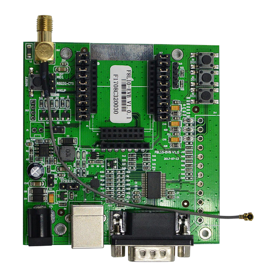
Chapter 1 Product Introduction 1.1 General The F8L10-EVB is a test and development board for LoRa modules. It features various interfaces including an antenna interface, JTAG interface, module SMT interface, module pin header interface, F8L10S-N interface, terminal interface, serial DB9 interface, USB interface, jumper interface, module antenna connector, etc. - Page 7 LoRa Develop Board User Manual 1. When powered by USB, short the jumper cap (J36) on the left side for module supply voltage of 5V and disconnect J11. Recommendation: This configuration board is designed for LoRa module development and testing purposes.
-
Page 8: Chapter 2 Interfaces
LoRa Develop Board User Manual Chapter 2 Interfaces 2.1 Antenna Interfaces The antenna interface features a standard SMA female connector. 2.2 JTAG Interfaces The JTAG interface is used for downloading chip programs, and it has two interfaces. One is a 5-pin single-row 2.0 interface (J10), as shown in Figure 2. Figure 2: JTAG Interface Pin Definitions... -
Page 9: Module Smt Interface
LoRa Develop Board User Manual 2.3 Module SMT Interfaces Module SMT interface consists of dual-row pins as shown in Figure 3. Figure 3: Module SMT Interface Pinout Note: Interface definitions can be referred to the F8L10D Module User Manual. 2.4 Module Pin Interface The module pin header interface is a 2x8 dual-row pin header, as shown in Figure 4. -
Page 10: F8L10S-N Module Pin Interface
LoRa Develop Board User Manual 2.5 F8L10S-N Module Pin Interface Module Pin Header Interface is a single-row pin header with a center-to-center spacing of 2.54mm, as shown in Figure 5. Figure 5: Module Pin Header Interface Note: Interface definitions can be referred to the F8L10S-N User Manual.2.6 Terminal Interface 2.6 Terminal Interface Terminal Interface is a combination of power, serial, I/O pins, and ADC. -
Page 11: Serial Db9 Interface
LoRa Develop Board User Manual Table 2-1: Terminal Interface Definitions Number Interface Name SMT Interface J14-1 VDD5 J14-2 J14-3 J14-4 NU_TXD USART_TX J14-5 NU_RXD USART_RX J14-6 NU_RTS USART_RT J14-7 NU_CTS USART_CT/IO1 J14-8 NU_ IO2 J14-9 NU_ IO1 J14-10 NU_ADC2 ADC2 J14-11 NU_ADC1 ADC1... - Page 12 LoRa Develop Board User Manual The structural dimensions of MM9329-2700/Murata are shown in Figure 8: Figure 8: Structural Dimensions of MM9329-2700/Murata...
-
Page 13: Chapter 3 Indicator Lights/Buttons
LoRa Develop Board User Manual Chapter 3 Indicator Lights/Buttons 3.1 Serial Communication Indicator Light The serial communication indicator will flash when the device's serial port is in communication. The indicator remains off when there is no communication. The circuit diagram is shown in Figure 9. Figure 9 Serial Communication Indicator 3.2 Three-channel I/O Interface Indicator Lights The indicator lights for the three I/O interfaces are controlled by transistors Q1, Q2, and Q3,... -
Page 14: Three-Channel Adc Pin Buttons
LoRa Develop Board User Manual Figure 10: Indicator Lights Controlled by Three I/O Interfaces 3.3 Three-channel ADC Pin Buttons The three ADC pin buttons are used for calibration. Press the corresponding button and use the software to calibrate the ADC value to its maximum when held down. Release the button and use the software to calibrate the ADC value to 0;... -
Page 15: Reset Button
LoRa Develop Board User Manual 3.4 Reset Button Reset Button is used to reset the LoRa module. When this button is pressed, the RESET pin is set to low, causing the LoRa module to stop running. When the button is released, the RESET pin is set to 3.3V, allowing the LoRa module to start and run its program.
Need help?
Do you have a question about the LoRa F8L10-EVB and is the answer not in the manual?
Questions and answers