
Subscribe to Our Youtube Channel
Related Manuals for Thermon TraceNet TC Series


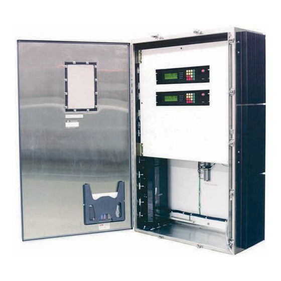
Summary of Contents for Thermon TraceNet TC Series
- Page 1 TraceNet™ TC Series Control System TCM18 Panel Installation, Start-Up, Operating, and Maintenance Guide Thermon, Inc. TraceNet™is a registered trademark of Thermon, Inc. PN 50316-0120...
- Page 2 The information in this guide is furnished for informational use only, is subject to change without notice, and should not be construed as a commitment by Thermon, Inc. Thermon assumes no responsibility or liability for any errors or inaccuracies that may appear in this guide.
-
Page 3: Table Of Contents
Contents Chapter 1: Introduction ..................Chapter 2: Specifications . - Page 4 Chapter 14: Notes ..................Chapter 15: More Information .
-
Page 5: Chapter 1: Introduction
2 or better. INITIAL INSPECTION AND HANDLING Upon receiving the TraceNet TC Series panel, it is important to confirm that the contents of the shipping containers agree with the shipping documents and with the purchase order. Also, it is important to check the shipped container exterior and packing materials for any possible freight damage. - Page 6 Where the panel has external heat sinks to dissipate the heat generated by solid state relay switching, it is recommended that a minimum of 6” (150 mm) of space be allowed between sinks and walls or other panels to minimize heat buildup at the heat sinks.
-
Page 7: Specifications
Specifications The general TraceNet TC Series panel specifications are as given below. Interior panel operating ambient range ◦ F to 140 ◦ F (-40 ◦ C to 60 ◦ ◦ ◦ ◦ ◦ Exterior panel operating ambient range F to 131... - Page 8 Current ratings in nonhazardous (ordinary) location based on TraceNet TC Series panels for up to 72 circuits are as follows For: 1 - 36 Circuits For: 37 - 72 Circuits Maximum Panel Exterior Maximum Allowable Average Amps per Relay ◦...
- Page 9 Auxiliary power output 24 Vdc at 0.5 Amps Panel ambient ◦ F (-40 ◦ C) to 131 ◦ F (55 ◦ operating temperature range ◦ F (-40 ◦ C) to 158 ◦ F (70 ◦ Storage temperature range Alarm relay outputs Option U 3 sealed dry contact relays rated 0.4A resistive at 24 Vdc Option A...
- Page 10 Power terminal connections 20 to 6 AWG (0.5 to 10mm ), 630V Printed circuit board conformally coated Alarm two 24 Vdc, 350 mA each * Rating based on heat sinks installed external to panel. Relay ratings have a reduced rating when sinks are used internal to panel. Higher voltage rating relays are also available as an option.
-
Page 11: Chapter 3: Module Connections
Module Connections Due to its flexible architecture, a variety of TraceNet TC Series panel configurations are available. The specific project drawings should be followed when installing the power supply and field distribution wiring into the TraceNet panel as well as when installing the data highway interface wiring. - Page 12 The TCM18 wiring and connections are located on the rear of the TCM18 module and are described as below: Figure 2: Wiring and Connection Details on the TCM18 PN 50316-0120...
- Page 13 The RTB6 Module Connections The RTB6 module allows the connection of six 3-wire 100 Ohm platinum RTD inputs to the TraceNet control system. The RTB6 circuit board is a passive device which communicates the discrete temperature inputs into a 26-pin bundled ribbon cable which then interconnects to a TCM18 module.
- Page 14 The PM6 Connections The PM6 serves as the heat trace power solid state switching module for a TraceNet TCM18 controller. It includes the heater and ground current measurement transformers, solid state heat trace control relays, and the heat dissipating heat sink.
- Page 15 Figure 5: RM6 Wiring and Connections Note: When receiving a new TraceNet TC Series control panel shipment, it is recommended that all module connections within the panel be re-torqued to the recommended tightness levels as provided in the project panel drawing and in Table 1 Chapter 4.
-
Page 16: Chapter 4: Field And Panel Wiring
Field and Panel Wiring For a successful installation of a TraceNet TC Series heat tracing control and monitoring panel, a number of equally critical parts of the system must be installed properly. Areas requiring close attention are the heat trace and insulation, the RTD temperature sensor installation, the distribution of the field RTD and power wiring, and the installation and routing of wiring inside the TraceNet panel. - Page 17 Figure 6: RTD Sensor Location Where limiter RTD sensors are installed on the process piping it should follow the guidelines above. In cases where the limiter is to be installed on the heater itself, it is important to recognize that an offset should be anticipated in the limiter trip value to allow for sensor reading error and overshoot.
- Page 18 Table 1: Recommended Torque Values TraceNet Panel Wiring TraceNet TC Series panels are configured and prewired into an integrated heat trace control and monitoring system. Clean terminal strips are provided to facilitate the field wiring into the panels. Refer to the project specific panel drawings when installing the field wiring within the panel.
- Page 19 Cables for RS485 Communication The following data highway cables listed in Table 2 are recommended. CableType Recommended 120 Ohm, -20 to +60 C 22AWG FHDPE Belden 3107A or equal insulation PVC outer jacket 120 Ohm, -30 to +80 C 24AWG PE Belden 9842 or equal insulation PVC outer jacket 120 Ohm, -70 to +200 C 24AWG Teflon...
-
Page 20: Chapter 5: Monitoring Heat Tracing Circuit Status
LCD display as shown in Figure 7 Figure 7: TCM18 Control and Monitoring Module Front Panel On power up, the TCM18 will display the following start-up screen message: THERMON TCM18 COPYRIGHT 2013 Figure 8: TCM18 Start-Up Screen PN 50316-0120... -
Page 21: Scan Mode
After this start-up message, the TCM18 will immediately proceed to operation in its SCAN MODE. The TCM18 will operate in a heat tracing circuit SCAN MODE during normal operation. That is, the LCD display will automatically scroll through each enabled heat tracing circuit number, indicating the actual measured temperature and the control set point for maintain temperature on the first two display screen lines. -
Page 22: High Temp Alarm
LOW TEMP The temperature being read on this circuit is below the ALARM value programmed as the lowest temperature allowed before an alarm condition should be reported. HIGH TEMP The temperature being read on this circuit is above the ALARM value programmed as the highest temperature allowed before an alarm condition should be reported. - Page 23 GND CURR When there is no TRIP function enabled, the second HHALARM level higher ground/earth leakage current alarm will automatically clear when second high ground/earth current alarm event clears. This event is reported as a GND CURR HHALARM (high-high alarm). LOW AMPS ALARM The amperage being read on this circuit is below the...
- Page 24 INVALID HI This warning message appears when the values that TEMP ALRM have been programmed into the high temperature alarm and trip settings are in conflict with maintain temperature and control band. Refer to Appendix A for details on the limitations on what high temperature alarm and trip values can be programmed into the TCM18 for a heat tracing circuit.
- Page 25 Figure 10: Common System, Alarm, and Trip LEDS To acknowledge an ALARM or TRIP event, press the ALARM ACK key on the touchpad. The first alarm condition will be indicated in the INFORMATION DISPLAY. Pressing the ALARM ACK key again will acknowledge the alarm. Repeat this sequence to determine the nature of any additional alarms as well as to acknowledge them.
- Page 26 Accessing Heat Tracing Circuit Information To access information on a specific heat tracing circuit, press the appropriate yellow or red key. Pressing these keys will directly access the information and functions associated with that key. As a typical example, press the MAINTAIN TEMP key as shown in Figure 11.
-
Page 27: Ground Current
CIRCUIT = 7 MAINTAIN TEMPERATURE ◦ MAINT= 49 Figure 12: TCM18 LCD Response A map of all the information and functions accessible in this manner is summarized in the following list. Touch Pad Key Information Display for Circuit in View Mode MAINTAIN TEMP The display screen provides heat tracing circuit number and the temperature control set point. - Page 28 CONFIG The first parameter line on the display screen indicates the TCM18 control instructions (ALL ON, ALL OFF, or BY CKT) for high ground/earth leakage current trip. The second and third lines indicate the control instructions for heater operating current and high temperature trip.
- Page 29 The third parameter line on this display screen indicates the amount of time delay (up to 30 minutes) that has been programmed in for a High Temperature Trip event. A value other than “0” for this parameter indicates the operator has chosen to provide a buffer to avoid tripping the heat tracing circuit for a short- term higher temperature exposure /operating event.
-
Page 30: Low Current Alarm
The second parameter line on this display screen indicates the temperature units to be displayed on the screen. Units to be displayed are either in degrees Fahrenheit or degrees Celsius. Note that these CONFIG settings are always global settings for all eighteen circuits on this controller. HEATER Indicates the heat tracing circuit number displayed, the ENABLE... - Page 31 Programming the TCM18 The TCM18 has an electronic password security provision. To access the programming mode, enter the 4-digit numerical security code. If no code has been entered, press the PROG key followed by the ALARM ACK key and subsequently followed by the PROG key.
- Page 32 Figure 13: TCM18 PROG Key The Display now reads as shown below: PROGRAM MODE ENABLED SELECT FUNCTION KEY Figure 14: Program Mode Enabled Press the MAINTAIN TEMP key. PN 50316-0120...
- Page 33 Figure 15: MAINTAIN TEMP Key The Display now reads as shown below with the flashing cursor I representing the active data entry field: PROGRAM CIRCUIT = 7I MAINTAIN TEMPERATURE ◦ MAINT= 49 Figure 16: Programming Maintain Temperature Pressing the green UP or DOWN Arrow programming keys followed by the green ENTER key allows the selection of the heat tracing circuit to program.
- Page 34 Figure 17: Programming Keys The display screen will now shift the cursor to the next value to program as shown in the following display. PROGRAM CIRCUIT = 7 MAINTAIN TEMPERATURE MAINT= 49 ◦ C← 49 ◦ Figure 18: Changing Maintain Temperature A single press of the green UP or DOWN arrow programming key will increase or lower the Maintain Temperature set point by a single degree.
- Page 35 Figure 19: The ENTER Key The DISPLAY screen now appears as shown in Figure 20. PROGRAM CIRCUIT = 7I MAINTAIN TEMPERATURE MAINT= 52 ◦ Figure 20: Selecting a New Circuit Number At this point, pressing the green UP or DOWN arrow key will select the next heat tracing circuit to program.
- Page 36 TIP: In many cases, the programmed value can be the same for a majority of heat tracing circuits. Note that when sequencing through the circuit numbers, there is an ALL option. This allows the programming of the same set point for all circuits on this particular TCM18 module and permits only entering the set point once.
-
Page 37: Control Band
Touch Pad Key Programmable Circuit Functions Sequence PROG plus This display screen indicates the heat tracing circuit MAINTAIN TEMP number selected. Using the UP or DOWN arrow, select the desired circuit number or ALL and press ENTER. The flashing cursor now moves to the temperature control set point (maintenance temperature). -
Page 38: Soft Start
The ON/OFF mode may be used with either mechanical relay or solid state relay heater current switching relays. SOFT START PROPORTIONAL control methods are only used with the zero crossing solid state current switching relay configurations as these control modes pulse power during start-up, power clamping, and also when employing a full proportional control algorithm. - Page 39 PROG plus This first display screen allows the programming of the CONFIG TCM18 control instructions (ALL ON, ALL OFF, or BY CKT) for high ground/earth leakage current (GND CUR TRIP), heater operating current (HTR CUR TRIP) and high temperature trip (HI TEMP TRIP). Noting the flashing cursor location, press the UP or DOWN arrow keys to select a new option and press ENTER to accept.
- Page 40 PROG plus Having completed selections on the first display CONFIG screen, the flashing cursor will move to the second display screen. This second display screen allows the programming of the TCM18 alarm relay configuration options (“ALARM RLY ALL ALARMS” or “ALARM RLY TEMP ONLY”).
- Page 41 The flashing cursor now moves to the next line which allows the operator of the TCM18 to program a certain amount of time delay for a High Temperature Trip event. A value other than 0 for this parameter indicates the operator has chosen to filter out and minimize tripping the heat tracing circuit for a short-term higher temperature exposure operating event.
- Page 42 The flashing cursor now moves to the next line which allows the operator of the TCM18 to program the amount of time in minutes (soft start time) over which the TCM18 will ramp up the power from 20% to 100% power clamp level.
- Page 43 1. ENABLED (selected for the normal control mode) 2. FORCED ON (typically selected to turn the heater on for diagnostic purposes). This setting will automatically revert back to the “ENABLED” status high temperature alarm event occurs and the ALARM ACK is pressed. As exceptions, when an auxiliary Forced Off switch is included and activated in the panel with the TCM18, all circuits will remain OFF during a Low...
- Page 44 4. 2 AMB (ambient sensing based on RTD1 and RTD2 on one or more of the heat tracing circuits). Refer to Part 8 for additional detail. 5. PIPE + AMB (single ambient sensing based on RTD1 controlling heater circuit with the second sensor RTD2 used as a high limiting alarm and trip sensor).
- Page 45 1. The data highway address (a value between 1 and 247) for the second RS485 port. 2. The communication protocol with the options being Modbus ASCII (7 bit, 2 stop bit, no parity format) or Modbus RTU (8 bit, 1 stop bit, no parity format) for the second port.
- Page 46 Press the PROG key at any point to exit from this sequence. If left in the program mode, the TCM18 will after a short wait automatically return to the SCAN mode. PROG plus HIGH A new display screen appears which indicates the TEMP ALARM HIGH TEMP SEEN value, which is the highest temperature...
- Page 47 PROG plus LOW This first display screen indicates the heat tracing TEMP ALARM circuit number selected. Using the UP or DOWN arrow select the desired circuit number or ALL and press ENTER. The flashing cursor moves to the present low temperature alarm value and allows the programming of the alarm set points by using the UP or DOWN key.
- Page 48 Press the PROG key at any point to exit from this sequence. If left in the program mode, the TCM18 will after a short wait, automatically return to the SCAN mode. PROG plus HIGH This display screen first indicates the heat tracing CURRENT circuit number selected.
- Page 49 PROG plus LOW This display screen first indicates the heat tracing CURRENT circuit number selected. Using the UP or DOWN arrow, ALARM select the desired circuit number or ALL and press ENTER. The flashing cursor moves to the present low current ALARM value and allows the programming of a new ALARM value by using the UP or DOWN key.
- Page 50 Heat Trace Control and Monitoring The TraceNet system allows a variety of control options for heat trace operation. The most energy efficient control mode is to use one or more process sensing RTD’s for each heat trace circuit. When configured with two RTD sensors, TraceNet will control off of the lowest reading and alarm off of the highest reading encountered.
- Page 51 As a third control mode option, which is a less energy conservative approach, the TraceNet TC Series panel may be configured for Ambient ON/OFF Control. In this case, one or two RTD’s may be used to sense ambient temperatures in the process area.
-
Page 52: Chapter 9: The Tcm18 In Process Sensing Applications
The TCM18 in Process Sensing Applications The TCM18 control module can be configured for process (pipe, vessel, or equipment surface) sensing with either a single RTD input (RTD 1 ribbon cable connections) for each heat tracing circuit or alternately it can be configured for dual RTD inputs (using both RTD1 and RTD2 ribbon cable connections in a TC Series panel where provision has been made to wire a second RTD for each heat tracing circuit). - Page 53 CIRCUIT = 12I HEATER SETUP HEATER = ENABLED RTD SETUP =1 PIPE Figure 23: Select Circuit Number At this point, the other options are to move to another CIRCUIT or to the ALL option through the use of the UP and DOWN arrow keys. In this case, select the green ENTER key to select this circuit.
- Page 54 CIRCUIT = 12 HEATER SETUP HEATER = ENABLED RTD SETUP =2 PIPE I Figure 25: Select RTD Setup With the circuit 12 now set up as a 2 RTD convention and with both of the RTDs installed in the appropriate RTB6 modules and the two ribbon cables connected into the back of the TCM18 into the RTD1/RC2 and RTD2/RC2 slots, the new set up is complete.
- Page 55 The TCM18 in Ambient Sensing Applications The TCM18 has a specially designed ambient sensing control algorithm to facilitate the ultimate in flexibility as to the number of ambient sensors and their various location placements within a TCM18 control and monitoring module. Details regarding these rules may be found in Appendix B.
- Page 56 PROG plus This sequence allows the programmer to select the CONTROL BAND type of ambient control desired on Circuit 1. The flashing cursor again requests the selection of the circuit number. Press the UP or DOWN arrow key to select Circuit 1. Press the ENTER key. The cursor moves to the CONTROL BAND line.
- Page 57 The TCM18 Data Highway Communications The TCM18 is provided with two RS485 communications ports. These ports allow for communication through Modbus ASCII or RTU protocols to a PC workstation and/or to the facility distributed control system (DCS). The TCM18 is also provided with an auxiliary 24 Vdc power source which can power optional communication converter modules which will accept the TCM18 data highway information and convert it to an alternate data stream protocol.
-
Page 58: Chapter 12: System Start-Up
System Start-Up All heat trace circuits should be properly terminated and meggered prior to energizing the heat trace power distribution and control panels. In addition, all pipes should be insulated and weather sealed to achieve the expected heat up and temperature maintenance performance of the system. Troubleshooting Tips When starting up a newly installed heat trace and control system, it is not uncommon to encounter numerous alarm and trip events. -
Page 59: Chapter 13: Maintenance
Maintenance Preventative maintenance consists of inspection, testing, checking connections, and general cleaning of equipment at scheduled intervals. The maintenance recommendations that follow are intended to support and in some cases “add to” those procedures detailed in the facility’s Planned Maintenance System (PMS). In case of conflicts, contact the project engineer for resolution. - Page 60 Maintenance Schedule Recommendation The service schedule is somewhat dependent on the “in service” hours. As a general rule, however, it is recommended that the heat tracing control and monitoring panel be serviced on a twelve-month basis to start. The schedule may be adjusted depending on the operating history of the panel and as the historical maintenance records dictate.
- Page 61 Touch up paint Machine oil Grease Electrical tape Refer to specific panel materials list for any tapes being used. Use only Thermon approved or equivalent materials. Damp cloth To avoid electrostatic discharge, clean window with damp cloth only. Recommended Visual Inspection Procedures...
- Page 62 • Check door hinges, latches, and other moving parts for proper operation. Use machine oil to lubricate the moving parts and restore proper operation where necessary. • Check for mechanical damage to any windows as well as check the window seals.
- Page 63 given in the following table. Tests Description Perform Self Test The Self Test function (accessed by pressing the CONFIG key) checks circuit breaker and output relay functionality. Perform SCAN Mode Review Operator should do a visual check for out of range temperatures and low or high heater and ground/earth leakage current in the heat tracing circuit(s).
- Page 64 Notes PN 50316-0120...
- Page 65 PN 50316-0120...
- Page 66 More extensive information about TraceNet and Thermon heat trace products may be downloaded at www.Thermon.com. Contact your nearest engineering service center for more detailed information regarding this specific project panel. In addition, Thermon’s product support group may be contacted for information of a more general nature. PN 50316-0120...
- Page 67 Appendix A Trouble Shooting Tips Troubleshooting tips are provided here as a beginning point in correcting start-up issues and clearing out alarm and trip events. High Temperature Reading/Alarm The following summarizes some of the possible causes and solutions for heat tracing high temperature alarms.
- Page 68 Improperly located RTD sensor. Is the RTD sensor installed next to a heated tank or a steam jacketed pump that might cause a higher than expected reading? Is the RTD sensor on the heater itself? Move the RTD sensor to location more representative of the majority of the piping.
- Page 69 Heat tracing over designed in heat output Review design as well as installation and or/ due to cable availability or natural instructions. Check heat tracing for design selections available. This can presence of proper current. Since result in higher than expected replacing the circuit may not be a temperatures due to overshoot desirable option here, the first approach...
- Page 70 Damaged, open, or wet thermal insulation Repair damage to insulation. does not allow the heat provided to hold the desired temperature. Wrong insulation size, type, or thickness Measure circumference of insulation, on all of circuit being traced. divide by π, and compare to insulation diameter charts for proper over sizing.
- Page 71 Permanent RTD sensors which enter the insulation at 90 degrees may be more sensitive to error associated with them depending on insulation installation or how well the sensor is physically attached. Adjust control set point to compensate for any accuracy offset. When using a 90-degree RTD probe for diagnostics, verify this measurement technique on a known pipe in the same...
- Page 72 RTD Sensor Alarm The following summarizes some of the possible causes and solutions for a heat tracing RTD sensor reading alarm. Cause Possible Solutions RTD connections are wired improperly or Confirm wiring and connections are have become loose. correct. RTD has failed open or has extremely Perhaps lightning has damaged the high resistance or RTD has failed shorted sensor? Maybe the piping has had some...
- Page 73 Circuit Fault Alarm The following summarizes some of the possible causes and solutions for heat tracing circuit fault alarms. Cause Possible Solutions Upon initial installation start-up, improper Confirm correct wiring and presence of wiring of the relay or low current in heater. the heater.
- Page 74 Self-regulating or power limiting heater Increase high current alarm set point (if may be operating at cooler than design approved by project engineer). pipe temperatures due to processing conditions and thus heaters may be drawing higher current values. Self-regulating or power limiting heater When reading current on one of these may be operating in its cold start regime.
- Page 75 Field heater wiring is improperly labeled Trace out the circuit wiring from the field and/or connected such that the heater back into the panel and subsequently to and the circuit number are not matched. the controller. Wherever possible, turn the circuit “off”...
- Page 76 Heat tracing cable may have been Replace heater. exposed to temperatures in excess of their maximum temperature ratings (excessive steam-out temperatures or upset process temperature events) and could have damaged the heater. Controller may be in error in reading cur- Use a different current clamp type meter rent.
- Page 77 Field heater wiring is improperly labeled Trace out the circuit wiring from the field and/or connected such that the heater back into the panel and subsequently to and the circuit number are not matched. the controller. Wherever possible, turn the circuit “off”...
- Page 78 (if approved by project engineer). If issues remain after exercising all these possible causes and solutions for heat tracing alarms and trips, contact your nearest Thermon engineering center for assistance and/or for arranging for field service. PN 50316-0120...
- Page 79 Appendix B Temperature and Current Limits The range of temperature, heater currents, currents and ground/earth leakage are tabulated in the below list. Parameters Limits TEMPERATURES All circuit temperature set points for the TCM18 should be programmed with the following limits: MinTemp <= LTA <...
- Page 80 HEATER MinCur <= LCA < HCA <= HCT <= MaxCur CURRENTS MinCur = 0 Amps = Low Current Alarm = High Current Alarm = High Current Trip (or HHAlarm) MaxCur = 100 Amps HEATER MinGndCur <= GCA <= GCT <= MaxGndCur CURRENTS MinGndCur = 20 mA = Ground Current Alarm...
- Page 81 Appendix C Advanced Features of the TCM18 Ambient Control The TCM18 has a specially designed ambient sensing control algorithm to facilitate the ultimate in flexibility as to the number of ambient sensors and their various location placements within a TCM18 control and monitoring module. This design algorithm uses the following set of rules in determining the sensor and associated control actions.
- Page 82 Rule Explanation All RTD sensors programmed for ambient sensing shall be located in ambients within the temperature range of -100F to +150F, or -73C to +65C. The RTD sensor for lowest numbered circuit within a specific TCM18 which has circuits programmed for ambient sensing becomes the system control RTD.
- Page 83 Circuit Number RTD Sensor Mode 1 AMB 1 AMB 2 AMB 1 AMB 2 AMB RTD#1 Input OPEN OPEN −10 −14 −8 RTD#2 Input OPEN −12 RTD#1 Reading Used a-10 −10 −14 −10 −8 RTD#2 Reading Used a-12 −12 Note: XX is an ignored RTD Input due to 1 AMB Mode Note that Circuit 2 RTD#1 is reading an ambient -10, so the TCM18 uses this RTD as the main RTD control sensor (SysAmbient1).
- Page 84 Appendix D Typical TCM18 Control Applications Example D1 - Ambient Sensing Freeze Protection - Proportional Control with Solid State Relay Output When configured with solid state relays, the TCM18 may be used in ambient sensing wide band proportional control. This method of control is ideal in tracing designs where simple ambient sensing RTD’s and freeze protection is required.
- Page 85 POWER PIPE/SURFACE TEMPERATURE DEGREES 100% CELSIUS PIPE/SURFACE TEMPERATURE HEATER POWER DEGREES CELSIUS Example D2 - Foundation Heave Protection - Proportional Control With Solid State Relay Output Cryogenic vessels and refrigerated rooms often utilize heating systems beneath to prevent heaving due to the freezing of the soil/foundation base structure. A typical heat tracing application of this type might require an operating tracing design as follows: Internal Room Temperature:...
- Page 86 The TCM18 control module using foundation temperature sensing RTD’s in each heating zone can be typically set at the control settings given below: Control Parameter Setting Controller Configuration Single RTD Input Control Method Proportional 100% Power On Temperature ◦ F (10 ◦...
- Page 87 POWER 100% TYPICAL SOIL CONTROLLED TEMPERATURE DEGREES CELSIUS Example D3 - Process Temperature Maintenance - Proportional Control With Solid State Relay Output The TCM18 features the option of proportional control for those applications where close temperature control is required on process piping which may have varying process temperature conditions.
- Page 88 The TCM18 control module utilizing pipe sensing RTD’s could be typically set as shown below: Controller Configuration Single RTD Input Control Method Proportional Maintain Temperature ◦ F (27 ◦ Control Band ◦ F (5 ◦ High Alarm Temperature ◦ F (32 ◦...
- Page 89 Example D4 - Process Temperature Control - Mechanical Relays Extremely versatile, the TCM18 can be configured with RM-6 mechanical relay output options. This option is often selected in high heat output tracing applications where either high current or high voltage switching is required. One such tracing application might be the temperature maintenance of a long sulfur transfer line.
- Page 90 PIPE TEMPERATURE DEGREES CELSIUS TIME -+ Example D5 - Process Temperature Control - Dual RTD Sensing It is sometimes considered advantageous to use dual RTD sensors on a critical heat tracing application such as a 50% caustic line. In this way, the power to the heater can be based on the input of two discrete temperature inputs rather than one.
- Page 91 The TCM18 control module utilizing pipe sensing RTD’s could be typically set as indicated below: Control Parameter Setting Controller Configuration Dual RTD Inputs Control Method Proportional Maintain Temperature ◦ F (27 ◦ Control Band ◦ ◦ F (3 High Alarm Temperature ◦...
- Page 92 Water Product Maintenance Temperature: ◦ F (10 ◦ Product Freeze Point: ◦ F (0 ◦ Heater Cable Type: Self Regulating Parallel Cable Number of Circuits: Ten Ambient Sensing 50% Caustic Product Maintenance Temperature: ◦ F (27 ◦ Product Freeze Point: ◦...
- Page 93 The heat tracing circuit control assignments would be as follows: Circuit No. Setting 1 thru 10 Enabled (Ambient Sensed Dual RTD’s) 11 thru 18 Enabled (Pipe Sensed Dual RTD’s) In this case, power relays on circuits 1 thru 10 will be controlling ambient sensed circuits based on the RTD input on Circuit 1 and specifically RTD#1 and RTD#2.
- Page 94 Appendix E Utilities The TCM18 has several utility functions which may be found to be useful on occasion. Touch Pad Key Programmable Circuit Functions Sequence PROG plus This display screen shows the internal RTD high ALARM ACK plus temperature reference resistor and low temperature ALARM ACK reference resistor “readings”...
- Page 95 Hazardous Locations (Potentially Explosive Atmospheres) This Appendix applies to TraceNet TC Series panels without purge equipment. The TC Series panels have been certified to be in compliance with IEC 60079-0: 2011, IEC 60079-15: 2010, EN 60079-0: 2012, and EN 60079-15: 2010.
- Page 96 Thermon, Inc. 100 Thermon Drive San Marcos Texas www.thermon.com Thermon PN 50316-0120...
Need help?
Do you have a question about the TraceNet TC Series and is the answer not in the manual?
Questions and answers