MSI MEGA 865 User Manual
Msi mega 865: user guide
Hide thumbs
Also See for MEGA 865:
- Quick installation manual (123 pages) ,
- Software installation manual (164 pages) ,
- Quick installation manual (184 pages)
Table of Contents
Advertisement
Quick Links
Advertisement
Table of Contents

Related Manuals for MSI MEGA 865


Summary of Contents for MSI MEGA 865
- Page 1 MEGA 865 User’ s Guide Version 1.2...
- Page 2 VOIR LA NOTICE D’ INSTALLATION AVANT DE RACCORDER AU RESEAU. Micro-Star International MEGA 865 This device complies with Part 15 of the FCC Rules. Operation is subject to the following two conditions: (1) this device may not cause harmful interference, and (2) this device must accept any interference received, including interference that may cause undesired operation.
-
Page 3: Lithium Battery Statement
Lithium Battery Statement CAUTION Danger of explosion if battery is incorrectly replaced. Replace only with the same or equivalent type recommended by the manufacturer. Discard used bat- teries according to the manufacturer’ s instructions. Macrovision Statement ® This product incorporates copyright protection technology that is protected by method claims of certain U.S. -
Page 4: Safety Instructions
Safety Instructions Always read the safety instructions carefully. Keep this User’ s Manual for future reference. Keep this equipment away from humidity. Lay this equipment on a reliable flat surface before setting it up. The openings on the enclosure are for air convection hence protects the equipment from overheating. -
Page 5: Revision History
Trademarks All trademarks are the properties of their respective owners. Intel and Pentium are registered trademarks of Intel Corporation. ® ® PS/2 and OS /2 are registered trademarks of International Business Machines ® Corporation. Windows 95/98/2000/NT/XP are registered trademarks of Microsoft Corporation. ®... -
Page 6: Table Of Contents
CONTENTS Chapter 1. Getting Started -------------------------------------------------------- 1-1 1.1 All-in-One Feature Set ------------------------------------------------- 1-2 Front Panel -------------------------------------------------------------- 1-3 Back Panel -------------------------------------------------------------- 1-3 1.2 System Specification --------------------------------------------------- 1-4 1.3 Performance PC ---------------------------------------------------------- 1-6 1.4 Hi-Fi Audio --------------------------------------------------------------- 1-8 Chapter 2. Introducing Mainboard ---------------------------------------------- 2-1 2.1 Mainboard Layout ------------------------------------------------------- 2-2 2.2 CPU ------------------------------------------------------------------------ 2-3 2.3 Memory ------------------------------------------------------------------- 2-3... - Page 7 2.7 Connectors -------------------------------------------------------------- 2-14 IDE Connectors: PIDE1&SIDE1 ----------------------------------- 2-14 FDD Connector: FDD1 --------------------------------------------- 2-14 Serial ATA RAID Connector: SATA1 ---------------------------- 2-15 TV-Tuner Card Connector: CN3 ---------------------------------- 2-15 CPU/System Fan Connectors -------------------------------------- 2-15 Color LED Connector: LCM1 ------------------------------------- 2-16 Card Reader Connector: CR1 ------------------------------------- 2-16 Hi-Fi Power Connector: PWR1 ----------------------------------- 2-16 Modem Module Connector: MDC1 (Optional) --------------- 2-17 Radio Antenna Connector: J1 ------------------------------------- 2-17...
- Page 8 3.9 PC Health Status ..............3-23 3.10 Frequency/Voltage Control ..........3-24 3.11 Load Default Setting ............3-26 3.12 Set Supervisor/User Password ..........3-27 Chapter 4. Using Audio Function ............4-1 4.1 Control Panel ............... 4-3 4.2 Remote Control ..............4-4 4.3 AC Power on ................
-
Page 9: Chapter 1. Getting Started
Getting Started Getting Started 1.1 All-in-One Feature Set 1.2 System Specification 1.3 Performance PC 1.4 Hi-Fi Audio... -
Page 10: All-In-One Feature Set
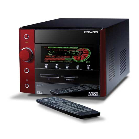
Chapter 1 1.1 All-in-one Feature Set The MEGA 865 implements all the Hi-Fi Stereo into Home-PC with a fancy color LED and control panel in the front bezel. When PC is powered off, you can use it just like a Hi-Fi Stereo with a remote controller. When PC is powered on, you can use it as a Home Theater or Media Center PC. -
Page 11: Getting Started
Getting Started Front Panel Backward Forward Mode Play/Pause Eject/Stop Hi-Fi Power Switch Shuttle Controller PC Power Switch Card Reader PC Reset (for Deluxe model) “Front I/O Cover” Release Button Front I/O Cover Back Panel Mouse LAN Port Parallel Port Power Jack R ad i o A n t en n a Jack Powe Voltage... -
Page 12: System Specification
® 2.8GHz Note: Please use a half-height AGP card with your Prescott CPU. (For the latest information about CPU, please visit our Web site at http://www. msi.com.tw/program/products/slim_pc/slm/pro_slm_cpu_support.php) Chipset: - Intel 865G + FW82801EB (Springdale G + ICH5) Memory: - DDR 400 x 2, support memory up to 2.0GB (Dual Channel support) On-Board Audio: - AC’... - Page 13 Getting Started Power Supply: - 250W (PFC 5V/12V SB) Full Range Chassis: - 202(W) x 320(D) x 151(H) mm On-Board Headers & Connectors - Rear Panel: Parallel Port x 1, VGA x 1, Serial Port x 1, PS/2 x 2, Mic in/Line in/ Line out x 1, USB x 2, LAN (RJ45) x 1, SPDIF/O x 1, Phone Jack (RJ11) x 1 - Front Panel: Mic-in x 1, Headphone x 1, USB x 2, SPDIF/I x 1, 1394 x 1 (4-pin), 1394 x 1(6-pin)
-
Page 14: Performance Pc
Chapter 1 1.3 Performance PC When PC is power on, the MEGA 865 is your performance PC. Power on means “If the power button of PC is pressed, the Hi-Fi stereo has no function even you press the Hi-Fi button.” However, you can still use the audio function through Windows Media Player and Mega Radio. - Page 15 -- The security features protect the data of machine from unauthorized access through BIOS control. Password -- The MEGA 865 uses two levels of BIOS access (User Password & Supervisor Password) to protect the computer system. Storage Subsystem 1) Hard Disk...
-
Page 16: Hi-Fi Audio
Chapter 1 1.4 Hi-Fi Audio When PC is powered off, the MEGA 865 can be used as a Hi-Fi audio. You can press the Hi-Fi button or use the remote control to start the audio function. Power-off means “When used as a Hi-Fi audio, the PC should be in power-off status. - Page 17 Getting Started MEGA 865 is equipped with SRS audio enforce- ment technology. SRS (Sound Retrieval System) was the first generation of 3D sound, dramatically improv- ing the quality of standard stereo. SRS is based on the human hearing system and was designed to re-...
-
Page 18: Chapter 2. Introducing Mainboard
Introducing Mainboard Introducing Mainboard Introducing Mainboard Introducing Mainboard Introducing Mainboard Introducing Mainboard 2.1 Mainboard Layout 2.1 Mainboard Layout 2.1 Mainboard Layout 2.1 Mainboard Layout 2.1 Mainboard Layout 2.2 CPU 2.2 CPU 2.2 CPU 2.2 CPU 2.2 CPU 2.3 Memory 2.3 Memory 2.3 Memory 2.3 Memory 2.3 Memory... -
Page 19: Mainboard Layout
Chapter 2 2.1 Mainboard layout MS-6797 v1.X Mainboard ○ ○ ○ ○ ○ ○ ○ ○ ○ ○ ○ ○ ○ ○ ○ ○ ○ ○ ○ ○ ○ ○ ○ ○ ○... -
Page 20: Cpu
Introducing Mainboard 2.2 CPU This mainboard supports Intel P4 Northwood up to 3.2GHz and Prescott ® up to 2.8GHz. The mainboard uses a CPU socket called PGA478 for easy CPU installation. When you are installing the CPU, make sure the CPU has a heat sink and a cooling fan attached on the top to prevent overheating. -
Page 21: Memory Speed/Cpu Fsb Support Matrix
Chapter 2 Memory Speed/CPU FSB Support Matrix Memory DDR266 DDR333 DDR400 FSB400 FSB533 FSB800 DIMM Module Combination Install at least one DIMM module on the slots. You can install either single- or double-sided modules in any order to meet your own needs. Memory modules can be installed in any combination as follows: Slot Memory Module... -
Page 22: Power Supply
Introducing Mainboard 2.4 Power Supply The system is equipped with a 250W(PFC) ATX power supply. The power cord of power supply has been connected to the connector JWR1 on the mainboard when shipped out. Except the 20-pin connector ATX1, you can find another 4-pin power connector JPW1 on the mainboard. -
Page 23: Front Panel
Chapter 2 2.5 Front panel The Front Panel is independent and extended from the mainboard. It’s connected to the Front I/O Connector on the mainboard. You can find the following ports on the Front Panel. Optical SPDIF-In USB x 2 J1394-1 J1394-2 Mic-In Head-Phone... -
Page 24: Ieee 1394 Port: J1394-1
Introducing Mainboard IEEE 1394 Port: J1394-1 The bigger 6-pin IEEE 1394 Port on the back panel is designed for you to connect to IEEE 1394 devices without external power. That means the mainboard can provide the power for the devices connected to this port. Software Support IEEE 1394 Driver is provided by Windows 98 SE, Windows... -
Page 25: Mic-In/Head-Phone
Chapter 2 Mic-in/Head-Phone Mic-in is a connector for microphone. Head-Phone is a connector for Speakers or Headphones. OPTICAL SPDIF-in The OPTICAL connector allows you to receive the audio file of SPDIF interface for recording and playing. The SPDIF (Sony & Philips Digital Interface) is developed jointly by the Sony and Philips corporations . -
Page 26: Back Panel
Introducing Mainboard 2.6 Back panel The Back Panel provides the following ports: Mouse Parallel Port LAN Port Serial Port Keyboard USB x 2 Line-in Mic-in VGA Port Optical SPDIF-out Speaker-out Serial Port The mainboard offers a 9-pin male DIN serial port . The port is 16550A high speed communication ports that sends/receives 16 bytes FIFOs. -
Page 27: Mouse/Keyboard Connectors
Chapter 2 Mouse/Keyboard Connectors The mainboard provides two standard mini DIN connectors for attaching PS/2 mouse and keyboard. You can plug a PS/2 mouse or keyboard directly ® ® into the connector. Pin Definition SIGNAL DESCRIPTION Mouse DATA Mouse DATA No connection Ground Mouse Clock... -
Page 28: Rj45 Lan Jack
Introducing Mainboard RJ45 LAN Jack The mainboard provides one standard RJ-45 jack for connection to Local Area Network (LAN). You can connect a network cable to the LAN jack. Pin Definition SIGNAL DESCRIPTION Transmit Differential Pair Transmit Differential Pair Receive Differential Pair Not Used Not Used Receive Differential Pair... -
Page 29: Parallel Port
Chapter 2 Parallel Port The mainboard provides a 25-pin female centronic connector as LPT. A parallel port is a standard printer port that supports Enhanced Parallel Port (EPP) and Extended Capabilities Parallel Port (ECP) mode. Pin Definition SIGNAL DESCRIPTION STROBE Strobe DATA0 Data0 DATA1... -
Page 30: Audio Port
Introducing Mainboard Audio Port Speaker-out is a connector for Speakers or Headphones. Line In is used for external CD player, Tape player, or other audio devices. Mic-in is a connec- tor for microphones. These three ports can also be used for 5.1 channel audio output. -
Page 31: Connectors
Chapter 2 2.7 Connectors IDE Connectors: PIDE1 & SIDE1 The mainboard has a 32-bit Enhanced PCI IDE and Ultra DMA 33/66/100 controller that provides PIO mode 0~4, Bus Master, and Ultra DMA/33/66/100 function. The two connectors on the mainboard allows you to connect to two IDE devices. -
Page 32: Serial Ata Raid Connector: Sata1
Introducing Mainboard Serial ATA RAID Connector: SATA1 The mainboard provides the connector to connect the hard disk of Serial ATA interface. One Serial ATA cable is included in the package. SATA1 Pin Definition Signal Signal TV-Tuner Card Connector: CN3 The mainboard provides the connector to connect the TV-Tuner card. You can insert the TV-Tuner card into the PCI Slot 1. -
Page 33: Color Led Connector: Lcm1
Chapter 2 Color LED Connector: LCM1 The connector is used to connect the color LED on the front panel. LCM1 VCC3SBY +12VSBY SPI Bus Key (0-~5) CD_SMI VCC5 HDLED PWRBTNH FP_RST LED-BL VCC5SBY Card Reader Connector: CR1 The mainboard provides a connector to connect the USB Card Reader (for Deluxe Model) on the Front Panel. -
Page 34: Modem Module Connector: Mdc1 (Optional)
Introducing Mainboard Modem Module Connector: MDC1 (Optional) The mainboard provides the connector to connect the modem module. The modem module is directly inserted into the connector without an extra cable. MDC1 Radio Antenna Connector: J1 The connector allows you to connect the radio antenna. Front Panel Power Connector: JFP1 The mainboard provides a Front Panel connector for electrical connec- tion to the Front Panel switches and LEDs. -
Page 35: Jumper
Chapter 2 2.8 Jumper There is a CMOS RAM on board that has a power supply from external battery to keep the data of system configuration. With the CMOS RAM, the system can automatically boot OS every time it is turned on. That battery has long life time for at least 2 years. -
Page 36: Slots
Introducing Mainboard 2.9 Slots PCI Slot The PCI slot allows you to insert PCI card or TV Tuner card. When adding or removing expansion cards, make sure that you unplug the power supply first. Meanwhile, read the documentation for the expansion card to make any neces- sary hardware or software settings NOTE: You can install the OPTIONAL MS8606 card into PCI 1... -
Page 37: Chapter 3: Setting Bios Function
Setting BIOS Function Setting BIOS Function Setting BIOS Function Setting BIOS Function Setting BIOS Function Setting BIOS Function 3.1 Entering Setup 3.1 Entering Setup 3.1 Entering Setup 3.1 Entering Setup 3.1 Entering Setup 3.2 The Main Menu 3.2 The Main Menu 3.2 The Main Menu 3.2 The Main Menu 3.2 The Main Menu... -
Page 38: Entering Setup
Chapter 3 3.1 Entering Setup Power on the computer and the system will start POST (Power On Self Test) process. When the message below appears on the screen, press <DEL> key to enter Setup. Press DEL to enter SETUP If the message disappears before you respond and you still wish to enter Setup, restart the system by turning it OFF and On or pressing the RESET button. -
Page 39: Getting Help
Setting BIOS Function Getting Help After entering the Setup menu, the first menu you will see is the Main Menu. Main Menu The main menu lists the setup functions you can make changes to. You can use the control keys ( ) to select the item. -
Page 40: The Main Menu
Chapter 3 3.2 The main menu Once you enter Phoenix-Award BIOS CMOS Setup Utility, the Main Menu ® (Figure 1) will appear on the screen. The Main Menu allows you to select from eleven setup functions and two exit choices. Use arrow keys to select among the items and press <Enter>... - Page 41 Setting BIOS Function Power Management Setup Use this menu to specify your settings for power management. PnP/PCI Configurations This entry appears if your system supports PnP/PCI. PC Health Status This entry shows your PC health status. Frequency/Voltage Control Use this menu to specify your settings for frequency/voltage control. Load Default Setting Use this menu to load factory default settings into the BIOS for stable system performance operations.
-
Page 42: Standard Cmos Features
Chapter 3 3.3 standard cmos features The items in Standard CMOS Features Menu are divided into 8 categories. Each category includes no, one or more than one setup items. Use the arrow keys to highlight the item and then use the <PgUp> or <PgDn> keys to select the value you want in each item. - Page 43 Setting BIOS Function If you select [Manual], related information is asked to be entered to the follow- ing items. Enter the information directly from the keyboard. This information should be provided in the documentation from your hard disk vendor or the system manufacturer.
-
Page 44: Advanced Bios Features
Chapter 3 3.4 advanced bios features Quick Boot Setting the item to [Enabled] allows the system to skip certain tests while booting. This will decrease the time needed to boot the system. Available options: [Enabled], [Disabled]. Full Screen LOGO Show This item enables you to show the company logo on the bootup screen. - Page 45 Setting BIOS Function CD-ROM Boot Priority Press [Enter] to enter a sub menu which shows every current CD-ROM installed. Use [PageUp] or [PageDown] key to select the first boot CD- ROM. 1st/2nd/3rd Boot Device The items allow you to set the sequence of boot devices where BIOS at- tempts to load the disk operating system.
- Page 46 Chapter 3 Hyper-Threading Technology The processor uses Hyper-Threading technology to increase transaction rates and reduces end-user response times. The technology treats the two cores inside the processor as two logical processors that can execute instructions simultaneously. In this way, the system performance is highly improved. If you disable the function, the processor will use only one core to execute the instructions.
-
Page 47: Advanced Chipset Features
Setting BIOS Function 3.5 advanced chipset features NOTE: Change these settings only if you are familiar with the chipset. DRAM Timing Selectable Selects whether DRAM timing is controlled by the SPD (Serial Presence Detect) EEPROM on the DRAM module. Setting to [By SPD] enables DRAM timings to be determined by BIOS based on the configurations on the SPD. - Page 48 Chapter 3 DRAM RAS# to CAS# Delay This field allows you to set the number of cycles for a timing delay between the CAS and RAS strobe signals, used when DRAM is written to, read from or refreshed. Fast speed offers faster performance while slow speed offers more stable performance.
- Page 49 Setting BIOS Function **On-Chip VGA Setting** The following items allow you to configure the settings about On-Chip VGA. On-Chip VGA This setting determines whether the system RAM can be allocated to on-chip video controller for video purposes. When setting to [Enabled], up to 128MB system RAM will be allocated to on-chip video controller.
-
Page 50: Integrated Peripherals
Chapter 3 3.6 integrated peripherals OnChip IDE Device Press <Enter> to enter the sub-menu and the following screen appears: IDE DMA Transfer Access This item is used to enable or disable the DMA transfer function of the IDE Hard Drive. The settings are: [Enabled], [Disabled]. 3-14 ○... - Page 51 Setting BIOS Function On-Chip Primary/Secondary PCI IDE The chipset contains a PCI IDE interface with support for two IDE channels. Select [Enabled] to activate the IDE interface. Select [Disabled] to deactivate this interface. **On-Chip Serial ATA Setting** On-Chip Serial ATA This setting is used to specify the SATA controller.
- Page 52 Chapter 3 Onboard Device Press <Enter> to enter the sub-menu and the following screen appears: USB Controller Select [Enabled] if your system contains a Universal Serial Bus (USB) controller and you have USB peripherals. USB 2.0 Controller This setting is used to enable/disable the onboard USB2.0 controller. This set- ting works only when the operating system installed supports USB2.0 driver, such as Windows 2000/XP/ME.
- Page 53 Setting BIOS Function connect audio connectors, set the field to [Disabled]. Setting options: [Disabled], [Auto]. AC97 Modem [Auto] allows the mainboard to detect whether a modem is used. If a modem is detected, the onboard AC’97 modem controller will be enabled; if not, it is disabled.
- Page 54 Chapter 3 Onboard FDC Controller Select [Enabled] if your system has a floppy disk controller (FDD) installed on the system board and you wish to use it. If you install add-on FDC or the system has no floppy drive, select [Disabled] in this field. The settings are: [Enabled] and [Disabled].
-
Page 55: Power Management Setup
Setting BIOS Function 3.7 Power management setup Sleep State This item specifies the power saving mode for ACPI function. If your operating system supports ACPI, such as Windows 98SE, Windows ME and Windows 2000, you can choose to enter the Standby mode in S1(POS) or S3(STR) fashion through the setting of this field. - Page 56 Chapter 3 Run VGABIOS if S3 Resume When Sleep State is set to [S3] or [Auto], users can select the options in this field. Selecting [Yes] allows BIOS to call VGABIOS to initializet he VGA card when system wakes up (resumes) from S3 sleep state. The system resume time is shortened when you disable the function, but system will need an AGP driver to initialize the VGA card.
- Page 57 Setting BIOS Function After AC Power Lost This setting specifies whether your system will reboot after a power failure or interrupt occurs. Available settings are: [Off] Leaves the computer in the power off state. [On] Leaves the computer in the power on state. ○...
-
Page 58: Pnp/Pci Configurations
Chapter 3 3.8 pnp/pci configurations This section describes configuring the PCI bus system and PnP (Plug & Play) feature. PCI, or Peripheral Component Interconnect, is a system which allows I/O devices to operate at speeds nearing the speed the CPU itself uses when communicating with its special components. -
Page 59: Pc Health Status
Setting BIOS Function 3.9 PC health status Current CPU/System Temperature, Current CPU/System FAN Speed, Vcore, +2.5V, Vcc, +3.3V, +5V, +12V, These items display the current status of all of the monitored hardware devices/ components such as CPU voltages, temperatures and all fans’ speeds. ○... -
Page 60: Frequency/Voltage Control
Chapter 3 3.10 Frequency/Voltage Control Auto Detect PCI Clk This option allows you to enable/disable the feature of auto detecting the clock frequency of the installed PCI bus. The settings are: [Enabled], [Disabled]. Spread Spectrum When the motherboard’s clock generator pulses, the extreme values (spikes) of the pulses creates EMI (Electromagnetic Interference). - Page 61 Setting BIOS Function PCI bus. It provides a method for end users to overclock the processor. Setting options: Give a DEC value by entering a number between maximum [233 MHz] to minimum [100 MHz]. ○ ○ ○ ○ ○ ○ ○ ○ ○ ○ ○ ○ ○ ○ ○ ○ ○ ○ ○ ○ ○ ○ ○ ○ ○ 3-25...
-
Page 62: Load Default Setting
Chapter 3 3.11 Load Default setting The default setting is the default value set by the BIOS vendor for stable system performance. When you select Load BIOS Setup Defaults, a message as below appears: Press [Y] to load the default values for the most stable system performance. 3-26 ○... -
Page 63: Set Supervisor/User Password
Setup. If set to [Setup], password prompt only occurs when you try to enter Setup. MSI Reminds You... About Supervisor Password & User Password: Supervisor password: Can enter and change the settings of the setup menu. -
Page 64: Chapter 4. Using Audio Function
Using Audio Function 4.1 Control Panel 4.2 Remote Control 4.3 AC Power on 4.4 Playing CD/MP3 in Hi-Fi Mode 4.5 Playing FM/AM in Hi-Fi Mode 4.6 Using Audio Function in Hi-Fi Mode 4.7 Using Audio Function in PC Mode... - Page 65 The MEGA 865 is featured with audio function. There are two ways to use audio function: in PC mode, in Hi-Fi mode. As the MEGA 865 is shipped out in barebone, you must install the necessary components (such as HDD, CPU, RAM...) before us- ing audio function in PC mode.
-
Page 66: Control Panel
Using Audio Function 4.1 Control Panel Backward Forward Mode Play/Pause Eject/Stop Hi-Fi Power Switch Shuttle Controller Deluxe model HiFi Power Start the audio function. Mode Choose the audio mode (CD/MP3, FM, AM) Eject the CD/MP3 or stop the play. In Hi-Fi Eject/Stop mode, you can press this button to recall memory sub-mode. -
Page 67: Remote Control
Chapter 4 4.2 remote Control The slim and subtle remote control embeds more than 30 buttons for your quick access. In Hi-Fi mode, you can control the play and EQ mode with one touch. Even in Media Center (PC mode), you can still fully control the multime- dia applications with the remote control. -
Page 68: Ac Power On
Using Audio Function 4.3 AC Power ON - Plug in the power cord After plugging in the power cord. You will see the panel (Color LED) items FLASH 3 times. - Set Timer Then you can adjust time by shuttle. You will see timer 00:00 flash. -
Page 69: Playing Cd/Mp3 In Hi-Fi Mode
Chapter 4 4.4 playing CD/MP3 in Hi-fi mode - Select CD/MP3 Press Hi-Fi button to start the audio function. Press MODE on the Control Panel to select CD/MP3 mode or press CD/MP3 on the remote control to play CD/MP3. If there is no CD in the tray or CD is broken, the Color LED shows “NO disc”. -
Page 70: Using Audio Function
Using Audio Function - Pause Music Press “Play/Pause” button to pause the music. - Play Next Song Press the “Forward” button to play the next song. - Replay the song Press “Backward” button once to re- play the song. - Replay previous song Press the “Backward”... - Page 71 Chapter 4 - Adjusting volume Turn the shuttle clockwise to turn the volume up and counterclockwise to turn the volume down. - Set Play Sub-Mode Press the shuttle once to set the Play Sub-Mode (NORMAL, : Allows you to play the CD in normal selection. RANDOM and REPEAT DISC) : Allows you to play the CD at random.
- Page 72 Using Audio Function - Set EQ Sub-Mode Turn the shuttle to choose EQ : To play the CD/MP3 in Normal mode. Su b- Mod e. T he i tem y ou choose will flash and the others : To play the CD/MP3 in POP mode. are on.
-
Page 73: Playing Fm/Am In Hi-Fi Mode
Chapter 4 4.5 playing FM/AM in hi-fi mode - Select AM/FM Press the “MODE” utton on the Con- trol Panel to set AM/FM mode or press AM/FM button on the Remote Control to switch to AM or FM station. - Next Available Station Press the “Forward”... - Page 74 Using Audio Function - Adjusting Volume Turn the shuttle to adjust the volume (3 steps). - Recall Memory Station Press the “Eject/Stop” once to recall the memory sub-mode and turn the shuttle to choose the number of spot (1-6) to play.
-
Page 75: Using Audio Function In Hi-Fi Mode
Chapter 4 4.6 Using audio function in Hi-Fi mode Radio Mode You can use the Remote Control or Front Panel to control the audio function. Remote Control Function 1. Press “Hi-Fi” button to turn on/off radio. 2. Press “FM/AM” button to listen to radio. 3. -
Page 76: Cd\Mp3 Mode
Using Audio Function Front Panel Function 1. Press “Hi-Fi” button to turn on/off radio. 2. Press “Mode” button to listen to radio. 3. Turn “Shuttle” to adjust the volume. 4. Press “Forward/Backward” button to get an available station. Memory Station The shuttle is not allowed to set the memory station as in Hi-Fi mode. - Page 77 Chapter 4 Front Panel Function 1. Press “Hi-Fi” button to turn on/off CD/MP3. 2. Press “FM/AM/CDMP3” button to select the mode you want. 3. Turn “Shuttle” to adjust the volume. 4. Press “Forward/Backward” button to get an available station. 6. Press “Play/Pause” button to play/pause the song. 7.
-
Page 78: Using Audio Function In Pc Mode
Using Audio Function 4.7 Using audio function in PC mode To listen to the play of CD/MP3 or radio in PC mode, you can use the Media Center Deluxe III. Radio Mode Click Radio to listen to broadcasts. See Section 5.4.6 Radio for details. 4-15... -
Page 79: Cd\Mp3 Mode
Chapter 4 CD/MP3 Mode Click Music to play music from your pre-programmed playlists or CDs. See Section 5.4.2 Music for details. 4-16... -
Page 80: Chapter 5: Media Center Deluxe Iii
Media Center Deluxe III Media Center Deluxe III 5.1 What is Media Center Deluxe III 5.2 Installing Media Center Deluxe III 5.3 Setting the Media Center Deluxe III 5.4 Using the Media Center Deluxe III 5.5 Using the Remote Control 5.6 Uninstalling... -
Page 81: What Is Media Center Deluxe Iii
Chapter 5 5.1 What is media center deluxe III Media Center Deluxe III is a brand-new platform for playing multimedia programs, including TV, radio, video, MP3, pictures and games. We have integrated all kinds of multimedia utilities into the Media Center Deluxe III. Instead of complicated operations and processes, there are only simple and bright buttons left on the Media Center Deluxe III, and what you need to do is just to click the button that is suitable for the aged and the children who are not familiar with the operating of the PC. - Page 82 Media Center Deluxe III 2. Enter user’ s information and serial number. The serial number can be found on the packing of the CD. Click Next to continue. 3. The Media Center Deluxe III will be installed to the default folder or your preferred one.
- Page 83 Chapter 5 4. It will be installed with the default title of MSI Media Center Deluxe III. You can edit a preferred title for it. Click Next to continue. 5. The status bar shows the installation process.
- Page 84 Media Center Deluxe III 6. Click Finish to complete the Media Center Deluxe III installation.
-
Page 85: Setting The Media Center Deluxe Iii
Chapter 5 5.3 Setting the media center deluxe III Once you have installed the Media Center Deluxe III, a pop-up window appears asking you to configure your system before entering the Media Center Deluxe III. OK to skip the process, and then change these settings in the Media You can cl i ck Center Deluxe III later. - Page 86 Media Center Deluxe III 5.3.1 General Check here Check here Set here Set here Hide Date & Time You can decide whether the date & time to be displayed on the top of your Media Center Deluxe III. Enable FullScreen Control You can check here to enable the full screen control.
- Page 87 Chapter 5 5.3.2 Pictures Check here Check here Set here Set here Play in Random Order Check the box next to this option, and the pictures will be played at random when using slideshow. Include Subfolders Check the box next to this option, and those pictures in the subfolders will be played when using slideshow.
- Page 88 Media Center Deluxe III 5.3.3 Television Select here Select here Select here Select here Select here Select here Select here Select here TV Source You can set the TV source. Option: Cable and Antenna. Country Select the country where you are. Capture Device This item will show the video capture chipset that your tuner card is using.
- Page 89 Chapter 5 Input Source You can choose the source of video from cable TV, video device with S-Video connector or video device with Composite connector. - Source from cable TV S-Video - Source from device which supports S-Video output Composite - Source from device which supports composite output Audio Device This item will show the audio chipset that your PC is using.
- Page 90 Media Center Deluxe III 5.3.4 DVD Select here Select here Select here Select here Select here Set here Audio Language The DVD will be played in the language that you choose, if supported. Subtitle The DVD will be played with the subtitle that you choose, if supported. Auto Resume The video will be played from the position that you choose.
- Page 91 Chapter 5 5.3.5 MediaLibrary Add / Delete Path The location of the media files can be added / delected in advanced. When playing multimedia files in the Media Center Deluxe III, those files in the locations above will be used. Click ReScan, the Media Center Deluxe III will resume the content of the media library.
- Page 92 Media Center Deluxe III 5.3.7 Radio Each area has its proprietary frequency range. If you are unable to receive some stations in your area, there might be the inporper setting in this option. Check the porper radio box to correct the problem. The range for each area is listed below: Others(Europe) --- 87.5 ~ 108.0 MHz Japan --- 76.0 ~ 91.0 MHz...
-
Page 93: Using The Media Center Deluxe
Chapter 5 5.4 using the media center deluxe III Click the Media Center Deluxe III icon on the desktop, the main page of the Media Center Deluxe III will show as below: Chapter 5.4.1 Chapter 5.4.2 Chapter 5.4.3 Chapter 5.4.4 Chapter 5.4.5 Chapter 5.4.6 Chapter 5.4.7... - Page 94 Media Center Deluxe III Settings Click AutoScan, it will automatically scan all available channels for content. The number of channels available varies depending on whether you are using an an- tenna or cable TV. While it is scanning for channels, each channel will briefly appear in the display window.
- Page 95 Chapter 5 Schedule Click Schedule to enter the recording schedule screen. Click Add to program a one time only/weekly/daily recording; in addition, you can click Delete or Modify to delete or modify the existen schedule. Click here Closed Caption In some area, the TV programs come with hided caption. Click Closed Caption to show or hide the caption.
- Page 96 Media Center Deluxe III 5.4.2 Music Click Music, you can play music from your pre-programmed playlists or CD. My Location The Media Center Deluxe III will play the music files from your optical drives. View Library The Library share the same content with that of the Microsoft Media Player ®...
- Page 97 Chapter 5 5.4.3 Pictures Click View Pictures, you can view pictures from a specified folder. Click here to view the picture in full s c r e e n . P r e s s E S C k e y resume Sort by Name / Sort by Date The pictures can be sorted by name or date as you like.
- Page 98 Media Center Deluxe III Click here to view the video clip in full screen. Press E S C k e y resume 5.4.5 DVD / VCD Click DVD / VCD to watch DVD ro VCD. Settings / Start LanguageMate Please refer to chapter 5.3.4. Vocal There are left, right and both vocal for your selection.
- Page 99 Chapter 5 5.4.6 Radio Click Radio to listen to broadcasts. Sort by Name / Frequency These stations can be sorted by name or frequency as you like. AutoScan When first launch the radio player, please click AutoScan to add all available stations to your station lists.
- Page 100 Media Center Deluxe III 5.4.7 Karaoke Click Karaoke to play Karaoke DVD/VCD. Settings / Start LanguageMate Please refer to chapter 5.3.4. Vocal There are left, right and both vocal for your selection. Sound Effect You can choose a virtual sound effect for the playing DVD / VCD. These virtual sound effects are None, Rock, Bass, Hall, Soft, Vocal, Echo and Karaoke.
- Page 101 Chapter 5 5.4.8 Application Click Application to quick launch an application. Click here to execute the application S et t i ng s Click Settings to edit the applications list. T h e l oc a t i o n o f t h e s h ort c u t s i n your s ystem T h e c u r r e n t...
- Page 102 Media Center Deluxe III 5.4.9 Setup Click Setup, the window shows step-by-step procedures guiding you to personalize your Media Center Deluxe III. Check the radio box Check the radio box Set the delay time Click here to continue Hide Date & Time You can decide whether the date &...
-
Page 103: Audio Device
Chapter 5 TV So urce You can set the TV source. Option: Cable and Antenna. Country Select the country where you are. Video Capture Device This item will show the video capture chipset that your tuner card is using. Input Source You can choose the source of video from TV cable, video device with S-Video connector or video device with Composite connector. - Page 104 Media Center Deluxe III may vary according to the hardware of your PC. Recording Quality This item allows you to set the quality of recording video. Transi tion Ti me You are allowed to set time for picture slideshow. Take the window above as an example, when you use slideshow to view pictures, the picture shifts to next one after 2 seconds.
- Page 105 Chapter 5 Click here to finish Audi o L anguage The DVD will be played in the language that you choose, if supported. Subti tl e Language The DVD will be played with the subtitle that you choose, if supported. Auto R esume The video will be played from the position that you choose.
- Page 106 Media Center Deluxe III 5.4.10 Exit Click Exit to exit the Media Center Deluxe III Setup menu. make your selection Standby: The system will enter the power saving mode. Shut down: The system will be powered off. Close: The Media Center Deluxe III application will be closed. Cancel: The Media Center Deluxe III Setup menu resumes.
-
Page 107: Using The Remote Control
Chapter 5 5.5 Using the remote Control You can use the attached remote control to control TV as you do in the living room. Check the following note if your remote control doesn’ t function. What if the TV Tuner Card is installed correctly... What if all necessary cables are connected... - Page 108 Media Center Deluxe III Press the Hi-Fi button under operating system to launch Media Center Deluxe III or PVS alone (if Media Center Deluxe III is not installed). If the PVS is not installed, the Hi-Fi button is void. Number Key You can enter the numbers of channel directly to shift to the channel you want.
-
Page 109: Uninstalling
Chapter 5 5.6 Uninstalling Follow the steps below to uninstall the Media Center Deluxe III: Click Control Panel icon in the Start menu. Find and double-click Add or Remove Programs icon. Double-click here Select the program that you want to remove. Click Change/Remove to continue. S e l e c t M e d i a Center Deluxe III and click here... - Page 110 Media Center Deluxe III 4. Please DO NOT REMOVE THE SHARED FILES. Always click No to continue. Click here when asking 5. Click Finish to complete the uninstallation. 5-31...
-
Page 111: Chapter 6: Wireless Lan Card (For Deluxe Model)
Wireless LAN Card Wireless LAN Card (for Deluxe Model) 6.1 Introduction 6.2 Wireless Network Utility 6.3 Encryption 6.4 Status 6.5 Information... -
Page 112: Introduction
Chapter 6 6.1 Introduction The Wireless LAN Card, compliant with IEEE802.11b, is a high-efficiency wireless adapter for wireless networking at home, in office or in public places. The data transfer rate can be auto-negotiated to 1, 2, 5.5Mbps or up to 11Mbps, and is compatible with any existing IEEE802.11b devices. - Page 113 Wireless LAN Card 6.1.1 Hardware Specifications Compliant Standards - IEEE802.11b Bus and Connector Types - 32-bit 3.3V Type IIIA - 124-pin Golden Finger Security Mechanism - Hardware-based WEP Privacy Operational Environment - Operational Temperature: 0~55 - Humidity: 10~90% (Non-Condensing) Weight and Dimension - Weight:12g - Dimension: 50.8 x 59.6 x 4.9mm 6.1.2 Radio Frequency Specifications...
-
Page 114: Wireless Network Utility
Chapter 6 6.2 Wireless network utility After installing the driver, the Wireless LAN Card provides a convenient and powerful utility that allows you to set up, configure, and know your network- ing status easily and clearly. 6.2.1 The Wireless LAN Icon - Not connected to the network. - Page 115 Wireless LAN Card Language You can select language according to your operating system. Switch to AP Mode (optional) If your wireless LAN adapter supports Software AP function, you can see this item in the sub-menu, and which allows you to use your wire- less adapter as a virtual access point.
- Page 116 Chapter 6 6.2.2 Changing the Control Setting(for Windows XP Only) If you use Windows XP, the wireless LAN is controlled by the operating system (default). To take full advantage of your wireless adapter, it is recommended to use the Wireless Network Utility to control your wireless LAN. To change the control setting: 1.
-
Page 117: Wireless Lan Card
Wireless LAN Card 3. Click Advanced, and the Properties window will appear as below. Uncheck this option Click 4. Uncheck the Use Windows to configure my wireless network settings option. Then, click OK. 5. Now, you can use the W ireless Network Utility to configure your network. -
Page 118: Networking
Chapter 6 6.3 networking Since the wireless LAN card is installed in your computer, you have to configure the settings for communication to start working in your network environment. 6.3.1 Infrastructure Mode Infrastructure mode allows your computer to communicate with the other com- puters in the network through an Access Point. - Page 119 Wireless LAN Card If you want to configure the network settings: 1. Click Advanced in the Wireless Network Connection window. 2. The Available Networks field contains a list of available Access Points in your network. Select (highlight) one network you want, and then click Configure to set up the selected network.
- Page 120 Chapter 6 4. Click OK. The selected network will appear in the Preferred Networks field. If it contains two or more networks in the list, you can use Move up/Move down to set the priority. Click 5. Click OK to complete the configuration, and an icon indicating connected to the network will appear in the status area.
- Page 121 Wireless LAN Card 6.3.2 Ad-hoc Mode Ad-hoc mode allows your computer to communicate directly with any computer installed with compatible wireless adapter. If you want to use the network in Ad-hoc mode: - All the computers connected should be set to Ad-hoc mode. - The computers have the same SSID (network name) setting.
- Page 122 Chapter 6 2. You can build up the Ad-hoc network by clicking Add in the Preferred Networks field. Click 3. Set up the Network Name (SSID) and Network Key (if needed) for the network. Then, check the This is a computer-to-computer [ad hoc] network;...
- Page 123 Wireless LAN Card 4. The Ad-hoc network will appear in the Available Networks field. Click OK, and an icon indicating connected to the network appears in the status area. Click connected 5. The computer set up with this Ad-hoc network in step 3 is the designated administrator of the network.
-
Page 124: Encryption
Chapter 6 6.4 Encryption In the wireless network environment, the administrator can set up password (Network Key) to protect the network from being attacked or unauthorized access. When building the network, you can set up 4 sets of WEP keys, which can be 5 characters (10 hex-adecimal digital) or 13 characters (26 hex-adecimal digital) and specify one of them to use. -
Page 125: Status
Wireless LAN Card 6.5 Status In the Status tab, you can configure more network settings. Signal Strength: shows the received signal strength level. Link Quality: shows the measured signal level and connection status. Channel Specifies the operating radio frequency channel in Ad-hoc mode, which should be set to the same channel as the other points in the wireless network. - Page 126 Chapter 6 It is not recommended to change these settings if you are not familiar with the advanced configuration. Fragmentation Threshold You may set the length of the fragment in this field. Please note that each fragment should not be larger than the Fragmentation Threshold. RTS/CTS Threshold You may set the length threshold.
-
Page 127: Information
Wireless LAN Card 6.6 information In the Information tab, you can get some information about the manufacturer, hardware and software. 6-17...
Need help?
Do you have a question about the MEGA 865 and is the answer not in the manual?
Questions and answers