
Summary of Contents for Sulzer NORDICWATER DynaSand DST07
- Page 1 Installation and Operation Manual DynaSand DST07/DS700 Continuous freestanding filter...
-
Page 2: About This Manual
IMPORTANT READ CAREFULLY BEFORE USE KEEP FOR FUTURE REFERENCE About this manual The purpose of this manual is to give you the most value out of your product. The manual contains information about the DynaSand and its components. It can help you decide what work needs to be done even if you choose to have it done by Nordic Water personnel. -
Page 3: Table Of Contents
TABLE OF CONTENTS 1 GENERAL DESCRIPTION ............................7 Intended use ................................7 Filtration process ..............................7 Airlift pump ................................9 Sand washer ................................ 11 2 HAZARD & SAFETY SIGNS............................14 Safety signs ................................14 3 SAFETY ..................................16 General safety precautions..........................16 Explosive environments ............................. - Page 4 7 INSTALLATION................................32 Preparations prior to erection........................... 32 7.1.1 Rubber couplings.............................32 Erection of filter..............................33 Earthing ................................34 7.3.1 Equipotential earth bonding ........................34 Levelling of steel filter............................34 Grouting of steel filter ............................34 Levelling of FRP filter............................35 7.6.1 Installing the brackets..........................35 Erection of several filters...........................
- Page 5 11 TROUBLESHOOTING ..............................62 11.1 The airlift pump is not lifting enough filter media..................62 11.2 Foreign objects in the filter ..........................63 11.2.1 Sludge suction ............................63 11.3 Head loss over filter bed is too high ......................... 65 11.4 Filter break-through or nonmoving filter bed ....................65 11.5 High turbidity in filtrate ............................
- Page 6 This page is intentionally left blank...
-
Page 7: General Description
CHAPTER 1 GENERAL DESCRIPTION... -
Page 8: Intended Use
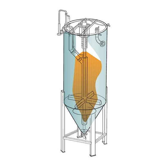
1 General description Filtration process The most common filter media is sand, but there are also other media available. Refer to the filter plant Before the incoming water is fed into the filter plant it specific information (separate documents) for the fil- should be pretreated by screening or similar to re- ter media at your plant. - Page 9 1 General description Figure 1.1 Principle of the filter Inlet valve Outlet 11. Wash water outlet Inlet pipe Airlift pump 12. Sand distributor Water distributor Upper part of the sand washer 13. Deaerator Filter bed (moving downwards) Sand washer 14. Head loss gauge Overflow weir 10.
-
Page 10: Airlift Pump
1 General description Airlift pump The airlift pump is positioned vertically in the guide tube (1) which will fix the pump in the correct position. The suction end of the airlift pump is located near the bottom of the filter. The pump lifts the sand to the sandwasher which is in the upper part of the filter, above the sand bed. - Page 11 1 General description Figure 1.3 B = Inlet of the airlift pump © Nordic Water Products AB, All Rights Reserved. DynaSand DST07 DS700 inst and oper manual EN. Rev: 10(75)
-
Page 12: Sand Washer
1 General description Sand washer The sand washer (9) consists of an inner ring-formed tube (15) and of several outer rings (16) put in a stain- less steel pipe. The slot in the sand washer is kept by the lock rings (17, 18). - Page 13 1 General description Figure 1.5 Figure 1.6 A = Filtrate level B = Wash water level © Nordic Water Products AB, All Rights Reserved. DynaSand DST07 DS700 inst and oper manual EN. Rev: 12(75)
- Page 14 CHAPTER 2 HAZARD & SAFETY SIGNS...
-
Page 15: Hazard & Safety Signs
2 Hazard & safety signs These hazard and safety signs are used in this man- ATTENTION ual and/or on the product. Indicates a situation that could cause serious dam- DANGER age to the product. Indicates a hazardous situation that, if not avoided, will result in death or serious injury. - Page 16 CHAPTER 3 SAFETY...
-
Page 17: Safety
3 Safety Only certified and qualified personnel can do the in- General safety precautions spection, monitoring and repairs. General and local Safe operation of the DynaSand can only be guaran- safety rules must be obeyed. teed if the product is correctly installed and the in- structions in this manual are obeyed. -
Page 18: Atex Marking
3 Safety 3.2.1 ATEX marking EC declaration DynaSand units intended for ATEX environments will bear the ATEX symbol along with an ATEX marking on the machine plate, describing type of protection and designated explosive atmosphere. The EC Declaration of Conformity is provided only if the supplied DynaSand is a ready-to-operate unit complete with the electrical control panel. -
Page 19: Environmental Conditions
CHAPTER 4 ENVIRONMENTAL CONDITIONS... - Page 20 4 Environmental conditions Table 4.1 General environmental conditions for the DynaSand M M a a t t e e r r i i a a l l M M a a x x i i m m u u m m w w a a t t e e r r t t e e m m - - A A m m b b i i e e n n t t t t e e m m p p e e r r a a - - M M a a x x i i m m u u m m a a l l l l o o w w e e d d w w i i n n d d s s p p e e e e d d p p e e r r a a t t u u r r e e [ [ °...
-
Page 21: Control System
CHAPTER 5 CONTROL SYSTEM... -
Page 22: Safety Precautions
5 Control system water is used as wash water to clean the media and Safety precautions carry the solids away. All kinds of installations, control and repairs on ma- chine/filter must be conducted by qualified personnel When a filter is taken out of operation, there will be a (e. -
Page 23: Air Quality Specification
5 Control system Air quality specification The compressed air supplied to the control cabinet in a filter plant shall meet the following minimum requirements. Table 5.1 Quality of compressed air in accordance with ISO 8573-1. Q Q u u a a l l i i t t y y P P o o l l l l u u t t a a n n t t s s W W a a t t e e r r O O i i l l... -
Page 24: Main Components Of A Pneumatic System
5 Control system Main components of a pneumatic • Air dryer or heat exchanger system • Pneumatic cabinet including: • Pressure switch (PS1), NC-potential free sig- The following is a schematic example of a pneumatic nal (not in the PSL cabinet) system. -
Page 25: Control Of The Pneumatic System
5 Control system Control of the pneumatic system manual and the technical specifications for the pneu- matic cabinet. 5.5.1 General The low pressure compressor The filter requires a constant flow of air for the airlift If a low pressure system is installed, the compressor pump when water is running through the filter. -
Page 26: Function Of The Pneumatic Cabinet
5 Control system 5.7.4 Function of the pneumatic cabinet continues for 15 min (adjustable) the operation of the filter plant should be stopped. The compressed air flowing through the pneumatic cabinet passes a pressure switch (PS1) which gives alarm at pressure loss. The compressed air then passes through a pressure reducing valve with a pressure gauge, a water sepa- rator and an air filter. - Page 27 5 Control system While waiting for the operation signal, the light ”Stand The ” ” T T E E S S T T ” ” position enables the filter to be run with- by” ( ( H H 1 1 ) ) is on. out an operating signal coming from the feed pump.
- Page 28 5 Control system Figure 5.5 The electrical cabinet. Transformer T1 Terminal strip Fuse F1/F2 10. Ground terminal Relay K1 Time relay K2 © Nordic Water Products AB, All Rights Reserved. DynaSand DST07 DS700 inst and oper manual EN. Rev: 27(75)
- Page 29 CHAPTER 6 DELIVERY, UNLOADING & STORAGE...
-
Page 30: Delivery, Unloading & Storage
6 Delivery, unloading & storage Delivery The filter is delivered secured on a wooden cradle, protected against dirt by a plastic cover. The filter is complete with all internal parts as- sembled, including the airlift pump. The hand rails for the service platform are fixed to the bottom of the fil- ter. -
Page 31: Storage
6 Delivery, unloading & storage Figure 6.2 Wooden case with accessories Figure 6.3 Wrapping Wooden crate Wooden crate with filter items and measuring tools Storage • Temperature: -10...+50°C or 14...122°F • Humidity: < 92 % relative humidity If you need to put the equipment into storage for some days or more, take precautions to prevent dam- If the DynaSand is to be put into storage for more than age to the equipment. -
Page 32: Installation
CHAPTER 7 INSTALLATION... -
Page 33: Preparations Prior To Erection
7 Installation Preparations prior to erection 7.1.1 Rubber couplings Before the filter is erected, check that the four rubber couplings (3) of the inlet pipe and the wash water out- let pipe are in position and that all clamps are prop- erly tightened. -
Page 34: Erection Of Filter
7 Installation Erection of filter Position the filter using the markings from 7.1 Prepa- rations prior to erection as guides. Raise the filter into a vertical position by lifting it from the lifting lugs. Two lifting straps, hoist cables or Secure the filter from falling before removal of lifting chains from the crane’s hook must be secured in the devices. -
Page 35: Earthing
7 Installation Earthing foundation with all anchoring bolts in each footplate. See the technical specification of the filter for maxi- mum allowed wind load on the filter. 7.3.1 Equipotential earth bonding ATTENTION Use an applicable equipotential earth-bonding system to protect the DynaSand and its equipment. This is Always consult the concrete designer/supplier con- very important to prevent galvanic corrosion and cerning the appropriate anchoring. -
Page 36: Levelling Of Frp Filter
7 Installation Levelling of FRP filter 5. Adjust the levelling bolts (6) so that the filter is standing in a vertical position. The filter must be placed on a flat and solid base that can take the total load of the filter. See the dimen- ATTENTION sional drawing for details. - Page 37 7 Installation Figure 7.4 Installation of brackets on the inside of the filter. Installation of brackets on the outside of the filter is also possible. Bracket Drainage Grout Foundation Levelling nut Levelling bolt Anchoring bolt © Nordic Water Products AB, All Rights Reserved. DynaSand DST07 DS700 inst and oper manual EN. Rev: 36(75)
-
Page 38: Erection Of Several Filters
7 Installation Erection of several filters height of the filters is adjusted so that the level differ- ence between the filtrate weirs does not exceed ± 5 Refer to 7.2 Erection of filter . Also observe the follow- ing: When installing several filters, make sure the Figure 7.5 Level of filtrate weirs, ±... -
Page 39: Assembly And Connection Of Pipes And Hoses
7 Installation Assembly and connection of pipes 5. Attach the dearation hose for the inlet pipe (10) with a hose clamp (some models only). and hoses Connecting the pipe lines 7.8.1 Assembling head loss gauge and • Inlet pipe (4) deaeration pipe •... -
Page 40: Connecting The Air Hoses
7 Installation Connecting the air hoses ATTENTION Attach the shut-off valve (3) of the air-lift pump on the Before filling with filter media, check that the sand flange of the filter (see figure). washer and the bottom cone are free from foreign objects that may disturb the operation. - Page 41 CHAPTER 8 FILLING OF FILTER MEDIA...
-
Page 42: Filling Of Filter Media
8 Filling of filter media The filter media is supplied in ~25 kg plastic bags, in General big bags containing ~1000-1500 kg or in bulk tankers. Depending of application the filter media can be dif- ferent kinds of sand or DynAktiv. Refer to the plant For plants with several filter units, the filling is nor- specific information (separate documents) for specific mally done pneumatically directly from the bulk... -
Page 43: Filter Media Specification
8 Filling of filter media Filter media specification S S a a n n d d Important for good filter performance is to use filter sand with appropriate particle size range, effective size and uniformity coefficient. The sand should be of hard, durable, and dense grains of natural sand (not crushed material) with rounded particles. -
Page 44: Before Filling
8 Filling of filter media Before filling CAUTION Chance of hazardous sand splashing, use eye pro- tection and breathing mask. 8.3.1 Cleaning and checking 1. Check that the sand washer, filter tank and bot- tom cone are free from foreign objects. Loosen the bottom flange and the screen (refer to Figure 8.2), flush the sand washer, tank and bot- tom cone with water. -
Page 45: Preparing The Filter For Filling Of Filter Media
8 Filling of filter media Figure 8.3 Lower part of the filter filled with water Sand distributor Water distributor Filling of filter media 8.4.1 Filling from bulk tanker When the filling is done pneumatically (from bulk tanker to filter(s)), the filter media must be wetted to Figure 8.2 Assembly of bottom flange with valve prevent dusting. -
Page 46: Checking The Amount Of Filter Media
8 Filling of filter media contents of the bags into the filter. Distribute the me- Table 8.2 Filling measure (A) (mm) for freestanding dia evenly over the cross section of the filter during filters and (C) (mm) for concrete plants. filling. - Page 47 8 Filling of filter media discharge pipe in the outlet of the airlift pump. Ex- tend the sand discharge pipe with a reinforced plastic or rubber hose to transfer the sand over the filter edge. Mount the air hose on the airlift pump again.
- Page 48 8 Filling of filter media Figure 8.6 Constant water level © Nordic Water Products AB, All Rights Reserved. DynaSand DST07 DS700 inst and oper manual EN. Rev: 47(75)
- Page 49 CHAPTER 9 AIRLIFT PUMP...
-
Page 50: Airlift Pump
9 Airlift pump Design The airlift pump consists of the below parts. Figure 9.1 Pump head with deaeration pipe Clamp Hole for air intake and air connection Air connection 10. Screen plate Air chamber Stabilizing pipes 11. O-ring Pump pipe O-ring Air hose ©... -
Page 51: How To Replace The Airlift Pump
9 Airlift pump How to replace the airlift pump Refer to Figure 9.2, Figure 9.3, Figure 9.4, Figure 9.5 and Figure 9.6. 1. Stop the feed to the filter. 2. Shut off the air flow to the airlift pump by closing the air valve. - Page 52 9 Airlift pump Figure 9.4 O-ring Airlift pump in operation position Guide tube Figure 9.3 Loosen the air hose here Splash hood © Nordic Water Products AB, All Rights Reserved. DynaSand DST07 DS700 inst and oper manual EN. Rev: 51(75)
- Page 53 9 Airlift pump Figure 9.5 Figure 9.6 Splash hood Air hose Sand discharge pipe Air channel O-ring Air nipple Pump pipe O-ring Clamp to lock the pump hose Screen plate © Nordic Water Products AB, All Rights Reserved. DynaSand DST07 DS700 inst and oper manual EN. Rev: 52(75)
-
Page 54: Start-Up And Operation
CHAPTER 10 START-UP & OPERATION... -
Page 55: Start-Up & Operation
10 Start-up & Operation For control of the air to the airlift pump, a pres- 10.1 General sure reducing valve (A) and a flow meter (B) are The performance of the filter is very much dependent located in the pneumatic cabinet (Figure 10.1). upon the characteristics of the incoming water, of Refer to 5.4 Main components of a pneumatic characteristics and concentration of suspended solids... - Page 56 10 Start-up & Operation Figure 10.1 © Nordic Water Products AB, All Rights Reserved. DynaSand DST07 DS700 inst and oper manual EN. Rev: 55(75)
-
Page 57: Sinking Speed Of The Filter Bed
10 Start-up & Operation 10.4 Sinking speed of the filter bed By using the sand measuring rod (H) with the centi- metre marked tape and a stop watch, the sinking speed of the filter bed can be checked. When the filter media is moving downwards, the measuring rod will follow. -
Page 58: Wash Water Flow Rate
10 Start-up & Operation 10.5 Wash water flow rate The wash water flow rate shall be 1.5– 2 times the sand flow rate. The amount of wash water can be measured either by using the measuring device (1) in the collecting vessel (2) or by collecting the wash water at its outlet. -
Page 59: Linegraph Of Wash Water
10 Start-up & Operation 10.5.1 Linegraph of wash water Figure 10.4 Figure 10.5 A = Example B = Time (seconds between (4) and (5) on the measuring device scale) © Nordic Water Products AB, All Rights Reserved. DynaSand DST07 DS700 inst and oper manual EN. Rev: 58(75) -
Page 60: Operation Settings
10 Start-up & Operation 10.6 Operation settings 1. Shut-off the feed inlet valve (A) for process water and the air supply (B) to the airlift pump. Due to process differences which can occur from one 2. Dirt deposited in the upper part (C) of the filter application to another, optimal settings vary greatly. -
Page 61: Restart Of Filter
10 Start-up & Operation 10.7.1 Restart of filter 1. Close the bottom valve. 2. Fill the filter to normal level with clean water. 3. Start the feed pump and the airlift pump. 4. Check that the filtrate is flowing over the overflow weir (F) into the outlet channel (G). -
Page 62: Troubleshooting
CHAPTER 11 TROUBLESHOOTING... -
Page 63: The Airlift Pump Is Not Lifting Enough Filter Media
11 Troubleshooting If the problem is not described in the following sec- tion, or if the described measure is not sufficient, con- tact Nordic Water. Spare parts must always be original spare parts from Nordic Water. 11.1 The airlift pump is not lifting enough filter media The air flow meter indicates low flow or no air flow at all. -
Page 64: Foreign Objects In The Filter
11 Troubleshooting 1. First, try to use the airlift pump for sucking up small objects. “Bump” the air flow at maximized air flow rate by turning the air valve off for about 30 seconds and then turning it on rapidly again. Repeat this action several times. - Page 65 11 Troubleshooting CAUTION Use protective gloves of rough rubber. Chance of scratch-wounds when reaching through the bottom flange. Figure 11.3 Foreign objects can be removed through the bottom flange (freestanding filters only) © Nordic Water Products AB, All Rights Reserved. DynaSand DST07 DS700 inst and oper manual EN. Rev: 64(75)
-
Page 66: Head Loss Over Filter Bed Is Too High
11 Troubleshooting 11.3 Head loss over filter bed is too high Observe that the head loss increases if the temperature of the feed decreases. Table 11.1 Steps to be taken when head loss is too high over the filter(s). C C h h e e c c k k S S t t e e p p s s t t o o b b e e t t a a k k e e n n Is the incoming flow too high? The filter should not be fed with higher flow than the designed maximum flow. - Page 67 11 Troubleshooting ATTENTION Do not insert air into the filter to clean or loosen up the media. Never insert air with an air lance into the filter bed or via the bottom drain, the air will dislocate the in- ternals and send filter media into the water distributor.
-
Page 68: High Turbidity In Filtrate
11 Troubleshooting 11.5 High turbidity in filtrate One or more of the parameters mentioned below may act together if the filtrate becomes turbid. If the steps be- low do not give the desired results, check with the Nordic Water representative. Table 11.3 Steps to be taken at high turbidity. -
Page 69: Control And Measuring Points
11 Troubleshooting 11.6 Control and measuring points Frequency of control is to be discussed and filled in below at start-up and possibly be adjusted later on. If there are periods of unusual loading, if the composition of the water is changing or if problems are observed, the fre- quency of control shall/might be increased. -
Page 70: Control And Measuring Values
11 Troubleshooting © Nordic Water Products AB, All Rights Reserved. DynaSand DST07 DS700 inst and oper manual EN. Rev: 69(75) -
Page 71: Control And Measuring Values
11 Troubleshooting © Nordic Water Products AB, All Rights Reserved. DynaSand DST07 DS700 inst and oper manual EN. Rev: 70(75) -
Page 72: Service Department
11 Troubleshooting 11.7 Service department For information about your local service office, contact the head service department in Sweden (refer to the contact information on page 1). © Nordic Water Products AB, All Rights Reserved. DynaSand DST07 DS700 inst and oper manual EN. Rev: 71(75) -
Page 73: Chapter 12 Accessories
CHAPTER 12 ACCESSORIES... -
Page 74: Accessories
12 Accessories 12.1 Accessories included in the delivery Figure 12.3 A brush (bottle brush) to be used for cleaning the head loss pipe (only included with freestanding filters) Figure 12.1 A sand measuring rod of aluminium for measuring the sinking speed of the filter bed Figure 12.4 Two pairs of pliers for mounting and dismounting the airlift pump Figure 12.2 A sand discharge pipe to be mounted in... - Page 75 This page is intentionally left blank...
- Page 76 last page H H e e a a d d O O f f f f i i c c e e S S e e r r v v i i c c e e a a n n d d S S p p a a r r e e P P a a r r t t s s Alfagatan 5 •...
Need help?
Do you have a question about the NORDICWATER DynaSand DST07 and is the answer not in the manual?
Questions and answers