
Subscribe to Our Youtube Channel
Related Manuals for Gravely Atlas JSV

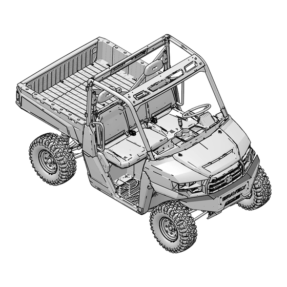
Summary of Contents for Gravely Atlas JSV
- Page 1 Atlas JSV ™ Owner/Operator Manual Models 996204 – Atlas JSV 3400 SD (SN 200101+) 996205 – Atlas JSV 3400 (SN 200101+) 996206 – Atlas JSV 3200 (SN 200101+) 996207 – Atlas JSV 6400 (SN 200101+) • 21902578 1/20 ENGLISH Printed in USA...
- Page 2 1916. Commercial-duty through and through, Gravely means business for lawn, turf and grounds maintenance professionals who work all day, every day. Be sure to visit us online at www. gravely. com for the latest news, new product introductions, upcoming events, career opportunities and more.
- Page 3 All information contained within this publication is based on the latest product information at the time of publication. Due to constant improvements in the design and quality of production components, some minor discrepancies may result between the actual vehicle and the information presented in this publication.
-
Page 4: Table Of Contents
Specifications ....139 Gravely Products ....147 Troubleshooting ....149 Warranty . -
Page 6: Introduction
INTRODUCTION INTRODUCTION IMPORTANT INFORMATION WARNING Failure to follow the warnings contained in this manual can result in severe injury or death. This vehicle is not a toy and can be hazardous to operate. This vehicle handles differently than other vehicles. A collision or rollover can occur quickly, even during routine maneuvers, if you fail to take proper precautions. -
Page 7: Safety Symbols And Signal Words
INTRODUCTION SAFETY SYMBOLS AND SIGNAL WORDS The following signal words and symbols appear throughout this manual and on your vehicle. Your safety is involved when these words and symbols are used. Become familiar with their meanings before reading the manual. DANGER DANGER indicates a hazardous situation which, if not avoided, WILL result in death or serious injury. -
Page 8: Vehicle Identification Numbers
INTRODUCTION VEHICLE IDENTIFICATION NUMBERS Record your vehicle's identification numbers in the spaces provided. The engine serial number is located on the side of the engine, below the injection pump. All keys have the number 4083. Remove the spare key and store it in a safe place. -
Page 10: Safety
A hard hat or helmet and approved eye protection are recommended when appropriate for working or riding conditions. Gravely recommends wearing approved eye protection bearing markings such as VESC 8, V-8, Z87.1 or CE. -
Page 11: Safety Labels And Locations
If an informational or graphic label becomes illegible or comes off, contact your Gravely dealer to purchase a replacement. Replacement safety labels are provided by Gravely at no charge. Each safety label’s location and part number are listed in this section of the manual. - Page 12 SAFETY • With more passengers than described in the Operation & Maintenance Manual, with children under the age of 12, and passengers who cannot comfortably reach the floor and hand holds with back against the seat. • With unapproved accessories - they may seriously affect stability. LOCATE AND READ OPERATION &...
- Page 13 SAFETY PROPER USE WARNING (3-SEAT) This label is located above the driver’s head on the front of the OPS frame. WARNING Require Proper Use of Your Vehicle Do your part to prevent injuries: • Do not allow careless or reckless driving. •...
- Page 14 SAFETY PAYLOAD WARNING This label is located above the driver’s head on the front of the OPS frame. MODEL NEVER EXCEED IF TOTAL PAYLOAD EXCEEDS JSV 3200 25 mph (40 kph) 830 lbs. (376 kg) JSV 3400 25 mph (40 kph) 830 lbs.
- Page 15 SAFETY LOAD/PASSENGER/TIRE PRESSURE WARNING The load/passenger/tire pressure warning label is located next to the fuel transport warning label in the cargo box. WARNING FALLING OFF CARGO BOX CAN CAUSE SERIOUS INJURY OR DEATH • Never carry riders in cargo box. OVERLOADING OR IMPROPER TIRE PRESSURE CAN CAUSE TIPPING OR LOSS OF CONTROL RESULTING IN SERIOUS INJURY OR DEATH •...
-
Page 16: Clutch Cover Warning
SAFETY CLUTCH COVER WARNING The clutch cover warning is located on the clutch cover. WARNING Improper service or maintenance of this CVT system can result in vehicle damage, SEVERE INJURY or DEATH. Always look for and remove debris inside and around clutch and vent system when replacing belt. - Page 17 SAFETY SHIFT CAUTION The shift caution is located above the ignition switch. CAUTION To avoid transmission damage, shift only when vehicle is stationary and at idle. When vehicle is stopped, place gear selector in PARK. TRAILER/HITCH CAPACITY LABEL The trailer/hitch capacity label is located on the rear hitch bracket. CAUTION HOT SURFACE.
-
Page 18: Operator Safety
• Always use the proper size and type of tires specified in this manual. Always maintain proper tire pressure as specified on safety labels. • Never modify this vehicle through improper installation or use of non-Gravely- approved accessories. • Always remove the key when leaving the vehicle unattended. -
Page 19: Operating Without Instruction
SAFETY • Always have this vehicle checked by an authorized Gravely dealer if it has been involved in an accident. • Always be alert for obstacles when operating this vehicle. Never attempt to operate over obstacles. • Never operate this vehicle on steep hills. -
Page 20: Seat Belts
SAFETY USING ALCOHOL OR DRUGS WARNING Never consume alcohol or drugs before or while operating this vehicle. Operating this vehicle after consuming alcohol or drugs could adversely affect operator judgment, reaction time, balance and perception. FAILURE TO INSPECT BEFORE OPERATING WARNING Failure to inspect and verify that the vehicle is in safe operating condition before operating increases the risk of an accident. - Page 21 SAFETY OPERATING WITH A LOAD ON THE VEHICLE The weight of the cargo, operator, and passengers impacts vehicle operation and stability. For your safety and the safety of others, carefully consider how your vehicle is loaded and how to safely operate the vehicle. Follow the instructions in this manual for loading, tire pressure, gear selection and speed.
- Page 22 SAFETY JUMPS AND STUNTS CAUTION Exhibition driving increases the risk of an accident or rollover. DO NOT do power slides, “donuts”, jumps or other driving stunts. Avoid exhibition driving. TURNING IMPROPERLY CAUTION Turning improperly could cause loss of traction, loss of control, accident or rollover.
-
Page 23: Operating Improperly In Reverse
SAFETY STALLING WHILE CLIMBING A HILL CAUTION Stalling or rolling backwards while climbing a hill could cause a rollover. Maintain a steady speed when climbing a hill. If you lose all forward speed: Apply the brakes gradually until the vehicle is fully stopped. Place the transmission in reverse and slowly allow the vehicle to roll straight downhill while applying light brake pressure to control speed. -
Page 24: Skidding Or Sliding
SAFETY SKIDDING OR SLIDING CAUTION Failure to use extra caution when operating on excessively rough, slippery or loose terrain could cause loss of traction, loss of control, accident or rollover. Do not operate on excessively slippery surfaces. Always slow down and use additional caution when operating on slippery surfaces. -
Page 25: Poor Visibility
SAFETY OPERATING ON FROZEN BODIES OF WATER WARNING Severe injury or death can result if the vehicle and/or the operator fall through the ice. Never operate the vehicle on a frozen body of water unless you have first verified that the ice is sufficiently thick to support the weight and moving force of the vehicle, you and your cargo, together with any other vehicles in your party. -
Page 26: Hot Exhaust Systems
EQUIPMENT MODIFICATIONS Do not install any non-Gravely-approved accessory or modify the vehicle for the purpose of increasing speed or power. Any modifications or installation of non- Gravely-approved accessories could create a substantial safety hazard and increase the risk of bodily injury. -
Page 28: Features And Controls
FEATURES AND CONTROLS FEATURES AND CONTROLS COMPONENT LOCATIONS Console Muffler (Spark Arrester) Headlights Receiver Hitch Radiator Front Bumper / Brush Guard OPS Cab Frame Fuel Cap Cargo Box Tailgate... -
Page 29: Auxiliary Outlets
FEATURES AND CONTROLS CONSOLE Light Switch Dump Box Switch (if equipped) Instrument Cluster Driver’s Side Auxiliary Outlet Ignition Switch Passenger Side Auxiliary Outlet Gear Selector (Shifter) Storage Compartment AWD Switch (if equipped) AUXILIARY OUTLETS The auxiliary outlets can be used to power standard 12V accessories like a cell phone charger or a power inverter up to 120 watts. -
Page 30: Adjustable Steering Wheel
GEAR SELECTOR Low gear is the primary driving range for the Atlas JSV. High gear is intended for use on hard-packed surfaces with light loads. Using high gear for heavy loads, hilly terrain or in wet, muddy conditions will increase the chance of drive belt slip. -
Page 31: Ignition Switch
FEATURES AND CONTROLS SWITCHES IGNITION SWITCH The ignition switch is a three-position, key-operated switch. The key can be removed from the switch when it is in the OFF position. The engine is off. Electrical circuits are off, except for the driver’s side auxiliary outlet and the Pulse Bar. - Page 32 FEATURES AND CONTROLS AWD SWITCH (IF EQUIPPED) The AWD switch has three positions: All Wheel Drive (AWD), Differential Lock/Two Wheel Drive (2WD) and Off (1WD/Turf Mode). Press the top of the switch to engage All Wheel Drive (AWD). Move the switch to the center position to lock the differential and operate in two wheel drive (2WD).
-
Page 33: Foot Pedals
FEATURES AND CONTROLS FOOT PEDALS BRAKE PEDAL Depress the brake pedal to slow or stop the vehicle. Apply the brakes while starting the engine. When the brake pedal is depressed, the brake light comes on. Check the brake light before each ride. 1. -
Page 34: Driver's Seat
EPS has shut down. Turn the key off and on to reset the unit. If the light remains on after starting the engine, the EPS system is inoperative. Your Gravely dealer can assist.. FUEL CAP The fuel tank filler cap... -
Page 35: Hood Latches
FEATURES AND CONTROLS OCCUPANT PROTECTION STRUCTURE (OPS) The Occupant Protection Structure (OPS) on this vehicle meets ANSI/OPEI B71.9 standards. Always have your authorized dealer thoroughly inspect the OPS if it ever becomes damaged in any way. No device can assure occupant protection in the event of a rollover. Always follow all safe operating practices outlined in this manual to avoid vehicle rollover. -
Page 36: Seat Belt Inspection
If any damage is found, or if the seat belt does not operate properly, have the seat belt system checked and/or replaced by an authorized Gravely dealer. 4. To clean dirt or debris from the seat belts, sponge the straps with mild soap... -
Page 37: Instrument Cluster
Fuel Gauge segments including the fuel icon will flash. Refuel immediately. A flashing wrench symbol alerts the operator that the preset service interval has been reached. Your Gravely dealer can provide scheduled Service Indicator maintenance. See page 49 for more information. -
Page 38: Indicator Lamps
Check vehicle if this warning appears. Serious engine Engine damage could result. Your authorized Gravely dealer can assist. This lamp will also illuminate if the vehicle is keyed on but not started; it will turn off once the vehicle is started. - Page 39 FEATURES AND CONTROLS the engine load should be reduced in any way possible to avoid overheating and shutting down the engine. This lamp illuminates if engine oil pressure drops below safe operating pressure. If this lamp illuminates while the engine is running, Low Oil turn the engine off as soon as safely possible Pressure...
-
Page 40: Display Area
FEATURES AND CONTROLS DISPLAY AREA 1 Pressing the MODE button will change the information displayed in Area 1 Speed Engine Temperature Ambient Temperature (Optional) - Page 41 FEATURES AND CONTROLS DISPLAY AREA 2 Toggle the Up/Down buttons to change the information displayed in Area 2 Odometer Engine Temperature Trip 1 Ambient Temperature (Optional)
- Page 42 FEATURES AND CONTROLS Trip 2 Voltage Speed Engine Hours Service Hours...
-
Page 43: Options Menu
FEATURES AND CONTROLS OPTIONS MENU Press and hold the MODE button to enter the Options Menu. OPTIONS MENU NOTES Diagnostic Codes Only displays if fault codes are present or stored Units - Distance Select MPH or KPH Units - Temp Select between °F and °C Clock Select between 12H or 24H, and set... - Page 44 FEATURES AND CONTROLS UNIT SELECTION DISTANCE 1. Press and hold the MODE button to enter the Options Menu. NOTICE “OPTIONS” will display on the screen for 3 seconds before showing first menu item. 2. Select “Units-Distance” from the Options Menu by pressing the MODE button.
- Page 45 FEATURES AND CONTROLS UNIT SELECTION TEMPERATURE 1. Press and hold the MODE button to enter the Options Menu. NOTICE “OPTIONS” will display on the screen for 3 seconds before showing first menu item. 2. Select “Units - Temp” from the Options Menu by pressing the MODE button. Reference the image shown above: Press the MODE button.
- Page 46 FEATURES AND CONTROLS CLOCK 1. Press and hold the MODE button to enter the Options Menu. NOTICE “OPTIONS” will display on the screen for 3 seconds before showing first menu item.
- Page 47 FEATURES AND CONTROLS 2. Select “Clock” from the Options Menu by pressing the MODE button. Reference the image shown above: Press the MODE button. Toggle the Up/Down Buttons to change the units (12H or 24H) With the correct unit displayed, Press the mode button which will set the unit.
-
Page 48: Back Light Color
FEATURES AND CONTROLS BACK LIGHT COLOR 1. Press and hold the MODE button to enter the Options Menu. NOTICE “OPTIONS” will display on the screen for 3 seconds before showing first menu item. 2. Select “Backlight Color” from the Options Menu by pressing the MODE button. -
Page 49: Back Light Level
FEATURES AND CONTROLS BACK LIGHT LEVEL 1. Press and hold the MODE button to enter the Options Menu. NOTICE “OPTIONS” will display on the screen for 3 seconds before showing first menu item. 2. Select “Backlight Level” from the Options Menu by pressing the MODE button. -
Page 50: Service Hours
FEATURES AND CONTROLS SERVICE HOURS 1. Press and hold the MODE button to enter the Options Menu. NOTICE “OPTIONS” will display on the screen for 3 seconds before showing first menu item. 2. Select “Service Hours” from the Options Menu by pressing the MODE button. Reference the image shown above: Press the MODE button. - Page 51 4. If the wrong PIN is entered, the screen will read WRONG PIN before going back to the ENTER PIN screen. If you forget your PIN, your authorized Gravely dealer can provide assistance. 5. If the correct PIN is entered, you will enter the Adjustable Speed Limiting menu.
- Page 52 FEATURES AND CONTROLS 6. To change the max speed: a. Press the MODE button on the MAX SPEED screen. b. Use the up and down buttons to toggle between the different settings: 15 MPH, 20 MPH, 25 MPH, 30 MPH, 35 MPH, or OFF. When MAX SPEED is set to OFF, the vehicle’s max speed is 40 MPH.
-
Page 53: Diagnostic Code
FEATURES AND CONTROLS DIAGNOSTIC CODE NOTICE Diagnostic Code Screen will show available MIL that has come on during that ignition cycle. 1. Press and hold the MODE button to enter the Options Menu. NOTICE “OPTIONS” will display on the screen for 3 seconds before showing first menu item. - Page 54 FEATURES AND CONTROLS DIAGNOSTIC DISPLAY CODE DEFINITIONS Open Load:There is a break in the wires that lead to the item listed in the chart (injector, fuel pump, etc.), or the item has failed. Short-to-Ground:The wire is shorted to ground between the electronic control unit and the item listed in the chart.
- Page 55 FEATURES AND CONTROLS DIAGNOSTIC CODES COMPONENT CONDITION Injector 1 (MAG) (SDI Driver Circuit Open/ Part Load) Grounded Driver Circuit Short to Driver Circuit Grounded Injector 2 (PTO) (SDI Driver Circuit Open/ Part Load) Grounded Driver Circuit Short to Driver Circuit Grounded Ignition Coil Primary Driver Circuit Short to...
- Page 56 FEATURES AND CONTROLS DIAGNOSTIC CODES COMPONENT CONDITION Driver Circuit Short to 1321 Driver Circuit 1321 Grounded Chassis Relay Driver Circuit Open/ 520208 Grounded Driver Circuit Short to 520208 Driver Circuit 520208 Grounded All Wheel Drive Driver Circuit Open/ 520207 Control Grounded Driver Circuit Short to 520207...
- Page 57 FEATURES AND CONTROLS DIAGNOSTIC CODES COMPONENT CONDITION EPS MODELS ONLY Vehicle Speed Sensor Data Valid But Above Normal Operational Range - Most Severe Level Data Erratic, Intermittent Or Incorrect Abnormal Rate Of Change Received Network Data In Error System Power Data Valid But Above Normal Operational Range - Most Severe...
- Page 58 FEATURES AND CONTROLS DIAGNOSTIC CODES COMPONENT CONDITION EPS MODELS ONLY Steering Torque Condition Exists 520223 Partial Failure Steering Torque Full Condition Exists 520224 Failure EPAS Inverter Data Valid But Above Temperature Normal Operational 520225 Range - Most Severe Level Data Valid But Above Normal Operating 520225 Range - Moderately...
-
Page 60: Operation
OPERATION OPERATION IMPORTANT INFORMATION WARNING Failure to operate the vehicle properly can result in a collision, loss of control, accident or rollover, which may result in serious injury or death. Read and understand all safety warnings outlined in the safety section of this owner’s manual. -
Page 61: Brake System Break-In
OPERATION BRAKE SYSTEM BREAK-IN Apply only moderate braking force for the first 50 stops. Aggressive or overly forceful braking when the brake system is new could damage brake pads and rotors. CONTINUOUSLY VARIABLE TRANSMISSION (CVT) BREAK-IN (CLUTCHES/BELT) A proper break-in of the clutches and drive belt ensures a longer life and better performance. -
Page 62: Safe Operation Practices
2. Engine exhaust fumes are poisonous. Never start the engine or let it run in an enclosed area. 3. Never operate with accessories not approved by Gravely for use on this vehicle. 4. Use caution and drive at reduced speeds in conditions of reduced visibility such as fog, rain and darkness. -
Page 63: Pre-Ride Inspection
OPERATION PRE-RIDE INSPECTION WARNING Failure to inspect and verify that the vehicle is in safe operating condition before operating increases the risk of an accident. Always inspect the vehicle before each use to make sure it's in safe operating condition. ITEM REMARKS PAGE... - Page 64 OPERATION ITEM REMARKS PAGE Seat Belt Check length of belt for damage, check latches page 35 for proper operation Grass and leaves Remove grass, leaves, foreign matter, and other flammable material or debris, especially near the exhaust system.
-
Page 65: Starting The Engine
OPERATION STARTING THE ENGINE 1. Position the vehicle on a level surface outdoors or in a well ventilated area. 2. Sit in the driver's seat and fasten the seat belt. 3. Place the transmission in PARK. 4. Apply the brakes. Do not press the throttle pedal while starting the engine. 5. -
Page 66: Cold Weather Operation
OPERATION COLD WEATHER OPERATION If the vehicle is used year-round, check the oil level frequently. A rising oil level could indicate the accumulation of contaminates such as water or excess fuel in the bottom of the crankcase. Water in the bottom of the crankcase can lead to engine damage and must be drained. -
Page 67: Engaging Awd
OPERATION ALL WHEEL DRIVE/REAR DIFFERENTIAL SYS- TEM (IF EQUIPPED) If your model is equipped with a lockable differential, you can choose to operate with an open differential or a closed differential. ENGAGING AWD NOTICE Switching to AWD while the rear wheels are spinning may cause severe drive shaft and clutch damage. -
Page 68: Disengaging Awd
OPERATION DISENGAGING AWD Move the AWD switch to the center or bottom position to disengage AWD. If the switch is turned off while the front hubs are driving, they will not release until the rear wheels regain traction. In some situations, the front gearcase may remain locked after turning the AWD switch off. - Page 69 OPERATION UNLOCKING THE DIFFERENTIAL (TURF MODE) When operating in TURF mode, the inside rear wheel will rotate independently from the outside wheel during turns. Operate in TURF mode only as needed to protect smooth, level surfaces from tire damage. DO NOT operate in TURF mode when climbing or descending hills, when sidehilling, or when operating on uneven, loose, or slippery terrain such as sand, gravel, ice, snow, obstacles, and water crossings.
-
Page 70: Driving Procedures
OPERATION DRIVING PROCEDURES 1. All riders should wear substantial footwear, long pants and a close-fitting shirt. A hard hat or helmet and approved eye protection are recommended when appropriate for working or riding conditions. 2. Perform the pre-ride inspection. 3. Sit in the driver's seat and fasten the seat belt. 4. -
Page 71: Driving On Slippery Surfaces
OPERATION DRIVING ON SLIPPERY SURFACES WARNING Skidding or sliding can cause loss of control or rollover (if tires regain traction unexpectedly). When operating on slippery surfaces such as ice or loose gravel, reduce speed and use extra caution to reduce the chance of skidding or sliding out of control. -
Page 72: Driving Downhill
OPERATION DRIVING ON A SIDEHILL (SIDEHILLING) Driving on a sidehill is not recommended. Improper procedure could cause loss of control or rollover. Avoid crossing the side of any hill unless absolutely necessary. If crossing a sidehill is unavoidable, follow these precautions: 1. -
Page 73: Driving Through Water
OPERATION DRIVING THROUGH WATER Your vehicle can operate through water up to a maximum recommended depth equal to the floorboards. NOTICE Immersion can result in major damage if the vehicle isn't serviced correctly and promptly. After immersion, always take the vehicle to your dealer service. Do not start the engine! If it's impossible to bring the vehicle to your dealer before starting the engine, perform the service outlined in the Vehicle Immersion section, and take the vehicle to your dealer at the first opportunity. -
Page 74: Driving In Reverse
OPERATION DRIVING IN REVERSE Follow these precautions when operating in reverse: • Always check for obstacles or people behind the vehicle. Always inspect left and right fields of vision before backing. • Always avoid backing downhill. • Back slowly. • Apply the brakes lightly for stopping. •... -
Page 75: Parking The Vehicle
OPERATION PARKING THE VEHICLE To park the vehicle, do the following: 1. Apply the brakes. Stop the vehicle on a level surface. 2. When parking inside a garage or other structure, be sure that the structure is well ventilated and that the vehicle is not close to any source of flame or sparks, including any appliance with pilot lights. -
Page 76: Hauling Cargo
OPERATION HAULING CARGO WARNING Hauling cargo improperly can alter vehicle handling and may cause loss of control or brake instability, which can result in serious injury or death. Always follow these precautions when hauling cargo: Never exceed the maximum weight capacity of the vehicle. When determining the weight you are adding to the vehicle, include the weight of the operator, passengers, non-factory installed accessories, loads in the rack or box and the load on the trailer tongue. -
Page 77: Load Capacity
TOTAL TOWED TOWED MAXIMUM TOTAL HITCH LOAD LOAD MODEL VERTICAL TOWING WEIGHT WEIGHT SPEED WEIGHT (LEVEL (15° GRADE) GROUND) Atlas JSV 2500 lbs. 850 lbs. 250 lbs 10 MPH 3200/3400/ (1134 kg) (386 kg) (113.4 kg) (16 km/h) 3400 SD/6400... -
Page 78: Dumping The Cargo Box
OPERATION DUMPING THE CARGO BOX DUMPING THE CARGO BOX (JSV 3200) To dump the cargo box, do the following: 1. Select a level site to dump the cargo box. Do not attempt to dump or unload the vehicle while parked on an incline. 2. - Page 79 OPERATION 5. Stand clear and pull up on the cargo box release lever . Lift the front of the cargo box to dump the cargo. 6. Lower the cargo box and push down securely to latch. WARNING Operating the vehicle while the cargo box is raised could result in severe injury. The box could close unexpectedly or impact overhead obstacles and cause injury to the driver or passengers.
- Page 80 OPERATION DUMPING THE CARGO BOX (JSV 3400, 3400 SD, & 6400) To dump the cargo box, do the following: 1. Select a level site to dump the cargo box. Do not attempt to dump or unload the vehicle while parked on an incline. 2.
- Page 81 OPERATION 6. Press and hold the bottom of the dump box switch to lower the cargo box. Release the switch when the box is fully seated on the frame, indicated by a ratcheting sound. 7. Close the tailgate and secure both tailgate latches. WARNING Operating the vehicle while the cargo box is raised could result in severe injury.
-
Page 82: Winch Guide
WINCH GUIDE WINCH GUIDE WINCH SAFETY These safety warnings and instructions apply if your vehicle came equipped with a winch or if you choose to add an accessory winch to your vehicle. WARNING Improper winch use can result in SEVERE INJURY or DEATH. Always follow all winch instructions and warnings in this manual. - Page 83 WINCH GUIDE 12. If winching at an angle is unavoidable, follow these precautions: a. Look at the winch drum occasionally. Never let the winch cable “stack” or accumulate at one end of the winch drum. Too much winch cable at one end of the winch drum can damage the winch and the winch cable.
-
Page 84: Winch Operation
WINCH GUIDE 22. Never winch the hook fully into the winch. This can cause damage to winch components. 23. Unplug the remote control from the vehicle when the winch is not in use to prevent inadvertent activation and use by unauthorized persons. 24. - Page 85 WINCH GUIDE 4. Always use the hook strap when handling the hook. WARNING Never put your fingers into the hook. This could lead to SEVERE INJURY. • Attach the hook itself onto the load or use a tow strap or chain to secure the load to the winch cable.
- Page 86 INJURY or DEATH in the event of failure. For your safety, always replace Gravely winch parts (including the cable) with genuine Gravely replacement parts available at your authorized Gravely dealer, or another qualified dealer. • If possible, keep the winch cable aligned with the centerline of the winching vehicle.
- Page 87 WINCH GUIDE 8. Read and adhere to the following information for winch damping to ensure safe winch use. a. In order to absorb energy that could be released by a winch cable failure, always place a “damper” on the winch cable. A damper can be heavy jacket, tarp, or other soft, dense object.
- Page 88 WINCH GUIDE j. Detach the winch cable hook. k. Rewind the winch cable evenly back onto the winch drum following the instructions in this manual. 12. Never attempt to winch another stuck vehicle by attaching the winch cable to a suspension component, brush guard, bumper or cargo rack. Vehicle damage may result.
-
Page 89: Winch Cable Care
Use of worn or damaged cable could lead to sudden failure and SEVERE INJURY. For your safety, always replace Gravely winch parts (including the cable) with genuine Gravely replacement parts available at your authorized Gravely dealer, or another qualified person. -
Page 90: Shock Loading
WINCH GUIDE SHOCK LOADING WARNING Your winch cable is very strong but it is NOT designed for dynamic, or “shock” loading. Shock loading may tension a winch cable beyond its strength and cause the cable to break. The end of a broken winch cable under such high loading can cause SEVERE INJURY or DEATH to you and other bystanders. -
Page 91: Winch Maintenance And Service Safety
3. Never work on your winch without first disconnecting the battery connections to prevent accidental activation of the winch. 4. For your safety, always replace Gravely winch parts (including the cable) with genuine Gravely replacement parts available at your authorized Gravely dealer, or another qualified person. -
Page 92: Emission Control Systems
EMISSION CONTROL SYSTEMS EMISSION CONTROL SYSTEMS NOISE EMISSION CONTROL SYSTEM Do not modify the engine, intake or exhaust components, as doing so may affect compliance with U.S.A. EPA noise control requirements (40 CFR 205) and local noise level requirements. OPERATION ON PUBLIC LANDS IN THE U.S.A. Your vehicle has a spark arrester that was tested and qualified to be in accordance with the USFS standard 5100-1C. -
Page 94: Maintenance
PERIODIC MAINTENANCE OVERVIEW Any qualified repair shop or person may maintain, replace or repair the emission control devices or systems on your vehicle. An authorized Gravely dealer can perform any service that may be necessary for your vehicle. Gravely also recommends Gravely parts for emissions-related service, however equivalent parts may be used for such service. -
Page 95: Break-In Period
MAINTENANCE BREAK-IN PERIOD The break-in period consists of the first 25 hours of operation. Careful treatment of a new engine and drive components will result in more efficient performance and longer life for these components. • Drive vehicle slowly at first while varying the throttle position. Do not operate at sustained idle. - Page 96 MAINTENANCE XU - PERFORM THESE PROCEDURES MORE OFTEN FOR VEHICLES SUBJECTED TO SEVERE USE. D - HAVE AN AUTHORIZED GRAVELY DEALER OR OTHER QUALIFIED PERSON PERFORM THESE SERVICES. E - EMISSION CONTROL SYSTEM SERVICE (CALIFORNIA) Break-In Service Item Action Air Filter / Air Box...
- Page 97 MAINTENANCE XU - PERFORM THESE PROCEDURES MORE OFTEN FOR VEHICLES SUBJECTED TO SEVERE USE. D - HAVE AN AUTHORIZED GRAVELY DEALER OR OTHER QUALIFIED PERSON PERFORM THESE SERVICES. E - EMISSION CONTROL SYSTEM SERVICE (CALIFORNIA) Service Item Action Air Filter / Air Box...
- Page 98 MAINTENANCE XU - PERFORM THESE PROCEDURES MORE OFTEN FOR VEHICLES SUBJECTED TO SEVERE USE. D - HAVE AN AUTHORIZED GRAVELY DEALER OR OTHER QUALIFIED PERSON PERFORM THESE SERVICES. E - EMISSION CONTROL SYSTEM SERVICE (CALIFORNIA) Shift Cable / Linkage Inspect; adjust as needed...
- Page 99 MAINTENANCE XU - PERFORM THESE PROCEDURES MORE OFTEN FOR VEHICLES SUBJECTED TO SEVERE USE. D - HAVE AN AUTHORIZED GRAVELY DEALER OR OTHER QUALIFIED PERSON PERFORM THESE SERVICES. E - EMISSION CONTROL SYSTEM SERVICE (CALIFORNIA) Service Item Action Air Filter / Air Box...
- Page 100 MAINTENANCE XU - PERFORM THESE PROCEDURES MORE OFTEN FOR VEHICLES SUBJECTED TO SEVERE USE. D - HAVE AN AUTHORIZED GRAVELY DEALER OR OTHER QUALIFIED PERSON PERFORM THESE SERVICES. E - EMISSION CONTROL SYSTEM SERVICE (CALIFORNIA) Front Gearcase Lubricant Change lubricant Front Wheel Bearings Inspect;...
- Page 101 MAINTENANCE XU - PERFORM THESE PROCEDURES MORE OFTEN FOR VEHICLES SUBJECTED TO SEVERE USE. D - HAVE AN AUTHORIZED GRAVELY DEALER OR OTHER QUALIFIED PERSON PERFORM THESE SERVICES. E - EMISSION CONTROL SYSTEM SERVICE (CALIFORNIA) Service Item Action Change Brake Fluid...
-
Page 102: Lubrication Recommendations
MAINTENANCE LUBRICATION RECOMMENDATIONS Check and lubricate all components at the intervals outlined in the Periodic Maintenance Chart, or more often under severe use, such as wet or dusty conditions. Items not listed in the chart should be lubricated at the general lubrication interval. -
Page 103: Engine Oil
Always perform the maintenance procedures as outlined in the Periodic Maintenance Chart. OIL RECOMMENDATIONS Gravely recommends using Gravely 5W-50 4-Cycle Oil or a similar oil. Refer to the Specifications chapter for capacities. See the Gravely Products chapter for the part numbers of Gravely products. - Page 104 MAINTENANCE 3. Raise the cargo box. Unlock the dipstick lever . Remove the dipstick and wipe it dry with a clean cloth. 4. Reinstall the dipstick and push it into place. Do not lock the dipstick. NOTE Make certain the dipstick is inserted all the way into the dipstick tube to keep the depth of the dipstick consistent.
-
Page 105: Engine Oil And Filter Replacement
MAINTENANCE ENGINE OIL AND FILTER REPLACEMENT Always change engine oil and filter at the intervals outlined in the Periodic Maintenance Chart. Always change the oil filter whenever changing the engine oil. The engine oil dipstick is located on the right front side of the engine. The engine oil fill cap is located on top of the valve cover. - Page 106 MAINTENANCE 7. Using the Oil Filter Wrench, turn the oil filter counter-clockwise to remove 8. Using a clean dry cloth, clean the filter sealing surface on the engine crankcase. 9. Lubricate the O-ring on the new oil filter with a film of fresh engine oil. Check to make sure the O-ring is in good condition.
-
Page 107: Gearcase Specification Chart
MAINTENANCE 20. When finished, reinstall the oil fill cap, oil dipstick and lock the lever. 21. Dispose of used oil and filter properly. GEARCASES GEARCASE SPECIFICATION CHART DRAIN PLUG/ FILL PLUG LEVEL GEARCASE LUBRICANT CAPACITY TORQUE CHECK PLUG TORQUE AGL Gearcase Transmission 41 oz. -
Page 108: Transmission Oil Change
MAINTENANCE TRANSMISSION OIL CHANGE The drain plug is located on the bottom of the gearcase. Access the drain plug through the hole in the skid plate. 1. Remove the fill plug 2. Place a drain pan under the drain plug 3. -
Page 109: Spark Plug Recommendations
Refer to the Specifications chapter for the recommended spark plug type for your vehicle. Always torque spark plugs to specification. NOTICE Using non-recommended spark plugs can result in serious engine damage. Always use Gravely-recommended spark plugs or their equivalent. SPARK PLUG GAP/TORQUE ELECTRODE GAP NEW OR USED PLUG TORQUE 0.85 mm Nominal... - Page 110 MAINTENANCE To inspect the spark plugs, do the following: 1. Lift the cargo box to access the spark plugs. 2. Remove the spark plug cap. Using the spark plug wrench provided in the tool kit, remove the plug by rotating it counter-clockwise. 3.
-
Page 111: Cooling System
Observe coolant levels and maintain as recommended by adding coolant to the overflow bottle. ADDING OR CHANGING COOLANT Gravely recommends using Gravely Antifreeze (part number 21901257 - 1 quart). This antifreeze is already premixed and ready to use. Do not dilute with water. -
Page 112: Radiator Coolant Level
But if the overflow bottle has run dry, the level in the radiator should also be inspected. 5. Reinstall the pressure cap. Use of a non-standard pressure cap will not allow the recovery system to function properly. Your Gravely dealer can provide the correct replacement part. - Page 113 MAINTENANCE OVERFLOW BOTTLE COOLANT LEVEL Always check and change the coolant at the intervals outlined in the Periodic Maintenance Chart. Maintain the coolant level between the minimum and maximum marks on the bottle (when the fluid is cool). 1. Position the vehicle on a level surface. 2.
-
Page 114: Belt Removal
• See your dealer or another qualified service person as outlined in this manual. • This CVT system is intended for use on Gravely products only. Do not install it in any other product. • Always make sure the CVT housing is securely in place during operation. - Page 115 MAINTENANCE 1. Remove the nine fasteners that retain the outer clutch cover. NOTE Removal of left rear wheel or left rear shock is NOT necessary for belt replacement. 2. To remove the clutch cover, pull the cover (starting at the bottom), lift up over the suspension, and then out of the vehicle.
- Page 116 MAINTENANCE 4. Insert clutch spreader tool into threaded hole on driven clutch as shown and turn clockwise to spread clutch. NOTICE The clutch spreader tool is found in the vehicle tool kit. 5. Walk the belt out of the driven clutch and drive clutch. Remove the belt from the vehicle.
-
Page 117: Belt Inspection
MAINTENANCE BELT INSPECTION To inspect the drive belt, do the following: 1. Inspect belt for hour-glassing (extreme circular wear in at least one spot and on both sides of the belt). Hour glassing occurs when the drive train does not move and the drive clutch engages the belt. - Page 118 MAINTENANCE 5. Install the clutch cover into wheel well by installing the top half first, then the bottom half over the suspension. NOTICE Use care when installing the clutch cover. Do not damage cover, intake boot, or electrical harness. 6. Install and torque the outer clutch cover bolts to specification.
- Page 119 MAINTENANCE CVT DRYING There may be some instances when water is ingested into the CVT system. Use the following instructions to dry it out before operating: 1. Position the vehicle on a level surface. 2. Remove the red drain plug on the outer clutch cover. Allow the water to drain completely.
-
Page 120: Vehicle Immersion
MAINTENANCE VEHICLE IMMERSION WARNING If your vehicle becomes immersed, major engine damage can result if the machine is not thoroughly inspected. Take the vehicle in for service before starting the engine. Your dealer can provide this service. If it's impossible to take your vehicle to a dealer before starting it, follow the steps outlined below: 1. -
Page 121: Filter Systems
MAINTENANCE FILTER SYSTEMS AIR FILTER REPLACEMENT Inspect the air filter at the intervals outlined in the Periodic Maintenance Chart. In extremely dusty conditions, air filter replacement will be required more often. 1. Locate the air filter on the left side of the unit. 2. - Page 122 MAINTENANCE 3. Remove the cover to access the air filter element 4. Inspect the airbox for oil or water deposits. Wipe away any deposits with a clean shop towel. IMPORTANT If the filter has been soaked with fuel or oil it must be replaced. DO NOT attempt to clean the air filter.
-
Page 123: Spark Arrester
MAINTENANCE SPARK ARRESTER WARNING • Never operate the vehicle without the spark arrester. • Remove any combustible materials from the area. Failure to heed the following warnings while servicing the spark arrestor could result in serious injury or death. • Never run the engine in an enclosed area. Exhaust contains poisonous carbon monoxide gas that can cause loss of consciousness or death in a very short time. -
Page 124: Brake Fluid
MAINTENANCE BRAKES The front and rear brakes are hydraulic disc type brakes. Press down on the brake pedal to engage the brakes. BRAKE FLUID Inspect the brake system routinely. Inspect the level of the brake fluid before each operation. WARNING After opening a bottle of brake fluid, always discard any unused portion. -
Page 125: Brake Inspection
MAINTENANCE BRAKE INSPECTION WARNING Do not apply WD-40 or any petroleum product to brake discs. These types of products are flammable and may also reduce the friction between the brake pad and caliper. 1. Check the brake system for fluid leaks. -
Page 126: Tire Tread Depth
Improper tire inflation or the use of non-standard size or type of tires may adversely affect vehicle handling, which could result in vehicle damage or personal injury. Always maintain proper tire pressure. Always use Gravely- approved size and type of tires for this vehicle when replacing tires. -
Page 127: Tire Rotation
MAINTENANCE TIRE ROTATION Tire rotation is recommended for every 500-mile (805-km) interval. Perform tire rotation on the vehicle by following the rearward cross strategy as shown. AXLE AND WHEEL NUT TORQUE SPECIFICATIONS Inspect the following items occasionally for tightness, and if they've been loosened for maintenance service. -
Page 128: Wheel Removal
MAINTENANCE WHEEL REMOVAL 1. Position the vehicle on a level surface. 2. Place the transmission in PARK. Stop the engine. 3. Loosen the wheel nuts slightly. 4. Elevate the side of the vehicle by placing a suitable stand under the frame. 5. -
Page 129: Headlight Bulb Replacement
MAINTENANCE LIGHTS Poor lighting can result in reduced visibility when driving. Headlight and taillight lenses become dirty during normal operation. Clean lights frequently and replace burned out lamps promptly. Do not operate this vehicle at night or in low light conditions until the headlight is replaced. Always make sure lights are adjusted properly for best visibility. -
Page 130: Headlight Adjustment
MAINTENANCE HEADLIGHT ADJUSTMENT NOTICE Include the weight of a rider on the seat while performing this procedure. To adjust the headlight beam, do the following: 1. Place the vehicle on a level surface with the headlight approximately 25 feet (7.6 m) from a wall. 2. - Page 131 MAINTENANCE FUSES If the engine stops or will not start, or if you experience other electrical failures, a fuse may need replacement. Locate and correct any short circuits that may have caused the blown fuse, then replace the fuse. The fuse box is located under the seat, next to the battery .
-
Page 132: Battery Removal
MAINTENANCE BATTERY Your vehicle has a sealed battery, which requires little maintenance. Always keep battery terminals and connections free of corrosion. If cleaning is necessary, remove the corrosion with a stiff wire brush. Wash with a solution of one tablespoon baking soda and one cup water. Rinse well with tap water and dry off with clean shop towels. -
Page 133: Battery Storage
Check battery voltage each month during storage and recharge as needed to maintain a full charge. Gravely recommends maintaining battery charge by using a battery tender charger or by charging about once a month to make up for normal self- discharge. - Page 134 MAINTENANCE STATE OF VOLTAGE ACTION CHARGE TIME* CHARGE None, check at 3 None required 100% 12.8-13.0 volts mos. from date of manufacture May need slight charge, if no 75%-100% 12.5-12.8 volts charge given, 3-6 hours check in 3 months Needs charge 50%-75% 12.0-12.5 volts 5-11 hours...
-
Page 135: Cleaning And Storage
• Air intake components If an informational or graphic label becomes illegible or comes off, you can purchase a replacement from your Gravely dealer. Always replace damaged or missing safety labels. Replacement safety labels are provided by Gravely at no charge. -
Page 136: Polishing The Vehicle
MAINTENANCE POLISHING THE VEHICLE Gravely recommends the use of common household aerosol furniture polish for polishing the finish on your Gravely vehicle. Follow the instructions on the container. POLISHING TIPS • Avoid the use of automotive products, some of which can scratch the finish of your vehicle. -
Page 137: Removal From Storage
3. Check all the points listed in the Pre-Ride Inspection on page 62. Tightness of the bolts, nuts and other fasteners should be checked by an authorized Gravely dealer or another qualified service facility. 4. Lubricate at the intervals outlined in the Periodic Maintenance section... - Page 138 MAINTENANCE TRANSPORTING THE ATLAS JSV Follow these procedures when transporting the Atlas JSV. 1. Place the transmission in PARK. 2. Stop the engine. 3. Slowly release the brake pedal and make sure the transmission is in PARK before exiting the vehicle.
-
Page 140: Specifications
SPECIFICATIONS SPECIFICATIONS ATLAS JSV 3200 / ATLAS JSV 3400 ATLAS JSV 3200 / ATLAS JSV 3400 Maximum Weight 1900 lbs. (861 kg) (including operator, passenger, Capacity cargo, accessories) Dry Weight 3200: 1570 lbs. (712 kg) 3400: 1620 lbs. (734 kg) GVWR –... - Page 141 SPECIFICATIONS ATLAS JSV 3200 / ATLAS JSV 3400 Stator Output 900 W @ 3000 RPM Compression Ratio 10.5:1 Starting System Electric Fuel System Electronic fuel injection Ignition Timing ECU Controlled 32° +/- 2° @ 5000 RPM Spark Plug/ Gap Autolite 5684 / 0.85 mm Nominal Front Suspension Dual A-arm w/ 9 in.
- Page 142 SPECIFICATIONS ATLAS JSV 3200 / ATLAS JSV 3400 Taillights 10 L.E.D. (.28W) Brake Light 10 L.E.D. (3.1W) ATLAS JSV 3400 SD ATLAS JSV 3400 SD Maximum Weight 1800 lbs. (816 kg) (including operator, passenger, Capacity cargo, accessories) Dry Weight 1790 lbs. (811 kg) GVWR –...
- Page 143 SPECIFICATIONS ATLAS JSV 3400 SD Displacement 999 cc Bore x Stroke 93 mm x 73.5 mm Stator Output 900 W @ 3000 RPM Compression Ratio 10.5:1 Starting System Electric Fuel System Electronic fuel injection Ignition Timing ECU Controlled 32° +/- 2° @ 5000 RPM Spark Plug/ Gap Autolite 5684 / 0.85 mm Nominal...
- Page 144 SPECIFICATIONS ATLAS JSV 3400 SD Brakes, Front/Rear Foot Activated, 4 wheel hydraulic disc Hood Headlight 4 single beam, 27W Taillights L.E.D. Brake Light L.E.D. ATLAS JSV 6400 ATLAS JSV 6400 Maximum Weight 2075 lbs. (941 kg) (including operator, passenger, Capacity...
- Page 145 SPECIFICATIONS ATLAS JSV 6400 Min. Turning Radius 154 in. (391 cm) Engine 4-Stroke SOHC Twin Cylinder Displacement 999 cc Bore x Stroke 93 mm x 73.5 mm Stator Output 900 W @ 3000 RPM Compression Ratio 10.5:1 Starting System Electric...
- Page 146 SPECIFICATIONS ATLAS JSV 6400 Tire Pressure - Front 10 psi (69 kPa) Tire Pressure - Rear 20 psi (138 kPa) Brakes, Front/Rear Foot Activated, 4 wheel hydraulic disc Hood Headlight 4 single beam, 27W Taillights 10 L.E.D. (.28W) Brake Light...
-
Page 148: Gravely Products
GRAVELY PRODUCTS GRAVELY PRODUCTS FLUID SERVICE PRODUCTS PART NUMBER DESCRIPTION Engine Lubricant 21900583 5W-50 4-Cycle Oil (qt./.95 L) Gearcase / Transmission Lubricants 21900585 Synthetic Transmission Fluid (qt./.95 21900586 All-Terrain Fluid (qt./.95 L) Coolant 21901257 Antifreeze (qt./.95 L) Additives / Miscellaneous... -
Page 150: Troubleshooting
TROUBLESHOOTING TROUBLESHOOTING DRIVE BELT WEAR/BURN POSSIBLE CAUSE SOLUTION Driving onto a pickup or tall Use low range during loading. trailer in high range Starting out going up a steep Use low range. incline Driving at low RPM or ground Drive at a higher speed or use low range more frequently. speed (3-7 MPH) Warm the engine at least 5 minutes. -
Page 151: Engine Backfires
TROUBLESHOOTING ENGINE DOESN'T TURN OVER POSSIBLE CAUSE SOLUTION Low battery voltage Recharge the battery Loose battery connections Check all connections and tighten Loose solenoid connections Check all connections and tighten Loose electronic control box Inspect, clean, reinstall connectors connections ENGINE TURNS OVER, FAILS TO START POSSIBLE CAUSE SOLUTION Out of fuel... -
Page 152: Engine Pings Or Knocks
TROUBLESHOOTING ENGINE PINGS OR KNOCKS POSSIBLE CAUSE SOLUTION Poor quality or low octane fuel Replace with recommended fuel Incorrect spark plug gap or Set gap to specs or replace plug heat range ENGINE RUNS IRREGULARLY, STALLS OR MISFIRES POSSIBLE CAUSE SOLUTION Fouled or defective spark plug Inspect, clean and/or replace spark plug... -
Page 153: Engine Stops Or Loses Power
TROUBLESHOOTING ENGINE STOPS OR LOSES POWER POSSIBLE CAUSE SOLUTION Out of fuel Refuel Kinked or plugged fuel vent Inspect and replace line Water is present in fuel Replace with new fuel Fouled or defective spark plug Inspect, clean and/or replace spark plug Worn or defective spark plug Your authorized dealer can assist wires... -
Page 154: Warranty
Contact your dealer for a copy of your registration. If you are not purchasing this machine through a dealer, you must have the vehicle inspected and set up by an authorized Gravely JSV Dealer. Failure to do so may void the warranty. Dealer set up is important to limit failure. - Page 155 WARRANTY • Have the warranty service performed by an authorized Gravely service representative. • Use lubricants, hydraulic fluid, and fuel as recommended in the Owner’s Manual. TO FIND AN AUTHORIZED SERVICE REPRESENTATIVE: In the U.S. and Canada: Use the dealer locator on our websites: www.ariens.com and www.gravely.
- Page 156 U.S.A. EPA EMISSIONS LIMITED WARRANTY This emissions limited warranty is in addition to the Gravely standard limited warranty for your vehicle. Gravely warrants that at the time it is first purchased, this emissions-certified vehicle is designed, built and equipped so it conforms with applicable U.S.
- Page 157 The exclusive remedy for breach of this limited warranty shall be, at the exclusive option of Gravely, repair or replacement of any defective materials, components or products. THE...
-
Page 158: Australian Consumer Law
Any qualified repair shop or person may maintain, replace, or repair the emission control devices or systems on your vehicle. An authorized Gravely dealer, or another qualified person, can perform any service that may be necessary for your vehicle. - Page 159 Some states do not allow limitations on how long an implied warranty lasts, so the above limitation may not apply to you. For further information, please contact Ariens at (888) 927-4367 or through www.gravely.com.
-
Page 160: Maintenance Log
MAINTENANCE LOG MAINTENANCE LOG MAINTENANCE LOG Use the following chart to record periodic maintenance. DATE MILES (KM) TECHNICIAN SERVICE PERFORMED / OR HOURS COMMENTS... - Page 162 Crankcase Emission Control System ........91 Adjustable Speed Limiting ... 50 Crossing Hillsides ...... 21 Adjustable Steering Wheel ..29 CVT Break-in......60 Age Restrictions ......18 CVT Drying ......118 Air Filter / Air Box..... 135 CVT System ......113 Air Filter Replacement ....120 All Wheel Drive/Rear Differential System (if equipped) .......
- Page 163 Equipment Modifications ..... 25 Display Area 1 ....... 39 Exhaust Emission Control Display Area 2 ....... 40 System ........91 Indicator Lamps ..... 37 Exposure to Exhaust ....25 Options Menu ......42 Overview ......36 Service Hours ......49 Unit Selection Distance ....
- Page 164 Throttle Pedal ......32 Clutch Cover Warning....15 Tire Rotation......126 Fuel Transport Warning.... 13 Tire Tread Depth ..... 125 Load/Passenger/Tire Pressure Tires ........125 Warning ......14 Towing Loads ......76 Payload Warning ....13 Towing the Atlas JSV....137...
- Page 165 Trailer Hitch Bracket....34 Transmission Drying .........118 Transmission Oil Change ..107 Transmission Oil Check .... 106 Transporting the Atlas JSV ..137 Towing the Atlas JSV..... 137 Turning Improperly..... 21 Unauthorized Use of the Vehicle ... 25 Vehicle Identification Numbers ..7 Vehicle Immersion ....119...
- Page 166 655 West Ryan Street Brillion, WI 54110 www.gravely.com WARNING Operating, servicing, and maintaining a passenger vehicle or off-road vehicle can expose you to chemicals including engine exhaust, carbon monoxide, phthalates, and lead, which are known to the State of California to cause cancer and birth defects or other reproductive harm.
Need help?
Do you have a question about the Atlas JSV and is the answer not in the manual?
Questions and answers
Warning lights and steering stiffens
Forgot my password on my jsv 3400 gravely atlas
What is the torque specs for the front hub castle nut on a Gravely JSV 6400? Thanks a bunch!