Table of Contents
Advertisement
03507454
Miraco Carrier Rev. (0)-2023
Smart
Link Control
50HZ
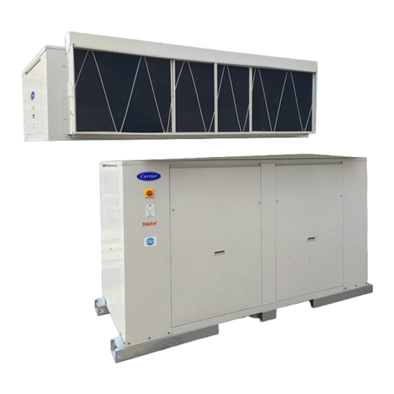
Vertical package / split air conditioners
38BB-N / 40AB-N Split Systems
50UB-N Vertical Packaged Systems
INSTALLATION, OPERATION AND
MAINTENANCE INSTRUCTIONS
the environmentally sound refrigerant
50UB-N 145 - 190 - 250 -300
Nominal cooling capacity 41.61 - 84.41 kW
Nominal heating capacity 15.00 - 22.50 kW
Miraco
Miraco
MISR REFRIGERATION & AIR CONDITIONING MFG. CO.
Advertisement
Table of Contents

Summary of Contents for MIRACO Carrier 38BB-N
- Page 1 38BB-N / 40AB-N Split Systems 50UB-N Vertical Packaged Systems 50UB-N 145 - 190 - 250 -300 Nominal cooling capacity 41.61 - 84.41 kW Nominal heating capacity 15.00 - 22.50 kW Miraco Miraco 03507454 Miraco Carrier Rev. (0)-2023 MISR REFRIGERATION & AIR CONDITIONING MFG. CO.
-
Page 4: Table Of Contents
Vertical package / split air conditioners 38BB-N / 40AB-N Split Systems 50UB-N Vertical Packaged Systems Contents 1. INTRODUCTION 2. OPERATING LIMITS 3. SAFETY ADVICE 4. UNIT IDENTIFICATION 5. AVAILABLE ASSEMBLIES 6. TRANSPORT AND HANDLING 7. TECHNICAL DATA - PACKAGE 8. TECHNICAL DATA - CONDENSING UNITS 9. -
Page 5: Introduction
1 - INTRODUCTION 2 - OPERATING LIMITS Carrier vertical packaged / split cooling only and cooling / Cooling Inlet air conditions heating ( with electrical heaters ) are compact air to air units, DBT (ºC) WBT (ºC) monobloc of vertical compact construction, designed to be Minimum installed indoors, outdoors according to site conditions, with Indoor... -
Page 6: Unit Identification
SAFETY ADVICE (Cont.) 5 - AVAILABLE ASSEMBLIES Refrigerant: Typical Installation (Vertical Packaged System) Important: These units contain R-410A, a fluorinated greenhouse gas covered by the Montreal protocol. (1) Two systems installed in interior zone of the motel with All interventions on the refrigerating circuit must be performed ducted evaporator air sections and through the wall in accordance with applicable legislation. -
Page 7: Transport And Handling
AVAILABLE ASSEMBLIES (Cont.) 6 - TRANSPORT AND HANDLING These machines must be unloaded and positioned by a spe- Versatility of Air Delivery cialist handling company using the appropriate, standardized - Split system is delivered from the factory with evaporator tools Important: the indoor module and outdoor module are supplied for building work installation as split version, and the unit having horizontal air discharge (case 1). -
Page 8: Technical Data - Package
7 - Technical Data - Package Vertical Packaged System Model 50UB145N-518C 50UB190N-518C 50UB250N-518C 50UB300N-518C Cool Only Split System Condensing Unit Model 38BB145N-518 38BB190N-518 38BB250N-518 38BB300N-518 Split System Evaporator Unit Model 40AB145N-518C 40AB190N-518C 40AB250N-518C 40AB300N-518C Vertical Packaged System Model 50UB145N-518E 50UB190N-518E 50UB250N-518E 50UB300N-518E Cool &... - Page 9 Technical Data - Package (Cont.) Vertical Packaged System Model 50UB145N-518C 50UB190N-518C 50UB250N-518C 50UB300N-518C Cool Only Split System Condensing Unit Model 38BB145N-518 38BB190N-518 38BB250N-518 38BB300N-518 Split System Evaporator Unit Model 40AB145N-518C 40AB190N-518C 40AB250N-518C 40AB300N-518C Vertical Packaged System Model 50UB145N-518E 50UB190N-518E 50UB250N-518E 50UB300N-518E Cool &...
-
Page 10: Technical Data - Condensing Units
8 - Technical Data - Condensing Units Split System Condensing Unit Model 38BB145N-518 38BB190N-518 38BB250N-518 38BB300N-518 Power Supply V/Ph/Hz 380 / 3 / 50 380 / 3 / 50 380 / 3 / 50 380 / 3 / 50 Manufacture Emerson Emerson Danfoss... -
Page 11: Condenser Coil
Technical Data - Condensing Units (Cont.) Split System Condensing Unit Model 38BB145N-518 38BB190N-518 38BB250N-518 38BB300N-518 Total Face Area m² 1.19 1.73 2.12 2.12 Number of Rows-Tube Diam. 5-3/8” 6-3/8” 6-3/8” 6-3/8” Number of Fins per Inch Condenser coil Type / Material Tubes Inner Grooved Copper Type / Material Fins Golden Corrugated Aluminum... -
Page 12: Technical Data - Evaporating Units
9 - Technical Data - Evaporating Units Evaporator - Cool Only 40AB145N-518C 40AB190N-518C 40AB250N-518C 40AB300N-518C Split System Evaporator-Cool & Heat with Electric heaters 40AB145N-518E 40AB190N-518E 40AB250N-518E 40AB300N-518E Manufacture Siemens Motor Type Three Phase Squirrel Cage Motor Power Supply V/Ph/Hz 380 / 3 / 50 Motor Electrical Connections Δ... - Page 13 Technical Data - Evaporating Units (Cont.) Evaporator Unit Model - Cool Only 40AB145N-518C 40AB190N-518C 40AB250N-518C 40AB300N-518C Split System Evaporator-Cool & Heat with Electric heaters 40AB145N-518E 40AB190N-518E 40AB250N-518E 40AB300N-518E Circuit 1: Gas line 1-1/8" 1-1/8" 1-1/8" 1-3/8” Circuit 1: Liquid line 5/8”...
-
Page 14: Detailed Dimensions ( Mm )
10 - Detailed Dimensions ( mm ) Size 145 Vertical Packaged Systems - Cooling Only 1599 1037 1012 1433 1720 1720 Split System – Evaporator Unit - Cooling Only 1599 1599 1014 1433 1720 1720 Split System – Condensing Unit 1599 1720 1720... - Page 15 Detailed Dimensions ( mm ) Size 145 Vertical Packaged Systems - Cooling / Heating ( with electrical heaters ) 1599 1155 1599 1130 1433 1720 1720 Split System – Evaporator Unit - Cooling / Heating ( with electrical heaters ) 1599 1124 1034...
- Page 16 Detailed Dimensions ( mm ) Size 190 Vertical Packaged Systems - Cooling Only 2125 2125 1181 1852 1155 2235 2235 Split System – Evaporator Unit - Cooling Only 2125 1852 1156 1082 2235 2235 Split System – Condensing Unit 2125 1105 2125 1800...
- Page 17 Detailed Dimensions ( mm ) Size 190 Vertical Packaged Systems - Cooling / Heating ( with electrical heaters ) 1292 2125 2125 1267 1852 1079 2235 2235 Split System – Evaporator Unit - Cooling / Heating ( with electrical heaters ) 2125 1953 1270...
- Page 18 Detailed Dimensions ( mm ) Sizes 250 & 300 Vertical Packaged Systems - Cooling Only 2525 2525 1161 2251 1079 2665 Split System – Evaporator Unit - Cooling Only 2525 1161 2525 1079 2251 2665 75.5 2665 Split System – Condensing Unit 2525 1105 2525...
- Page 19 Detailed Dimensions ( mm ) Sizes 250 & 300 Vertical Packaged Systems - Cooling / Heating ( with electrical heaters ) 2525 2525 1281 1197 2665 2665 Split System – Evaporator Unit - Cooling / Heating ( with electrical heaters ) 2525 2525 1264...
-
Page 20: Air Flow Performance Data
11 - Air Flow Performance Data Evaporator Fan Performance Data If other static pressure and airflow combinations are required to balance ductwork, select evaporator blower speed in accordance with Fan Performance Table. All units are factory set to give 100% nominal flow and static pressure values and these may be varied by means of the adjustable motor pulley. - Page 21 Air Flow Performance Data Condenser Fan Performance Data If other static pressure and airflow combinations are required to balance ductwork, select condensing blower speed in accordance with Fan Performance Table. All units are factory set to give 100% nominal flow and static pressure values and these may be varied by means of the adjustable motor pulley.
-
Page 22: Electrical Data
12 - Electrical Data Vertical Packaged System Model 50UB145N-518C 50UB190N-518C 50UB250N-518C 50UB300N-518C Cool Only Split System Condensing Unit Model 38BB145N-518 38BB190N-518 38BB250N-518 38BB300N-518 Split System Evaporator Unit Model 40AB145N-518C 40AB190N-518C 40AB250N-518C 40AB300N-518C Vertical Packaged System Model 50UB145N-518E 50UB190N-518E 50UB250N-518E 50UB300N-518E Heat Pump with Split System Condensing Unit Model 38BB145N-518... -
Page 23: Transport And Handling
13 - TRANSPORT AND HANDLING Fig. - Rigging (50UB-N) 13.1 - Discharge via crane The outdoor module can be lifted up by a crane, The slings will be hooked to the two mounting holes located on each crossbar. A rocker arm, as well as approved slings, both suitable for the dimensions and weight of the unit, must be used in order to carry out the work safely. -
Page 24: Weight Distribution, Kg (Approx.)
TRANSPORT AND HANDLING (Cont.) 13.3 - Centers of gravity Weight distribution, kg (approx.) 50UB-N ( all sizes) Control box Support point 38BB-N ( all sizes) Condensing Evaporator Packaged Section Section Section Control box Support Centre of Condensing Evaporator Packaged point gravity Unit Unit... -
Page 25: Location And Assembling
14 - LOCATION AND ASSEMBLING 14.2 - Installation of modules in split version 14.1 - Choice of location In this case follow general recommendations described When choosing the location, whatever may be the selected previously. fashion, the following precautions have to be taken into con- The indoor module can be attached to the ceiling using the sideration: threaded rod:... -
Page 26: Condensing Unit
LOCATION AND ASSEMBLING 14.4 - Recommended service clearance (mm) 50UB-N 145 1000 38BB-N 1000 40AB-N Packaged Unit Condensing Unit Evaporator Unit * Service space behind the unit depends on whether or not the unit is installed with outdoor air ducts. It is also necessary to leave space for cleaning and inspection of the outdoor heat exchanger. -
Page 27: Standard Components
15 - STANDARD COMPONENTS Package (1) Liquid Line (2) Condenser Unit Chassis (3) Suction Line (4) Evaporator Unit Chassis (5) Evaporator Right Suction Line (6) Evaporator Left Suction Line (7) Right Filter Liquid Line (8) Left Filter Liquid Line... -
Page 28: Commissioning
16 - COMMISSIONING NOTE: Under no circumstance the unit shouldn’t be started without having read the brochure completely. 16.1 - Electrical connections - Timer ON / OFF - Auto restart function with backup memory. 16.1.1 - Installation norms When the power failure is happened during the air conditioner operation, the microprocessor of the printed To perform the electric installation of the unit (cable glands, circuit board will memorize the operation setting. - Page 29 COMMISSIONING (Cont.) 16.2 - Checks in the centrifugal fans If the unit includes centrifugal fan for indoor module: - Check the blade rotation direction and that the axis turns without strokes nor vibrations. - Once running, check the operation conditions: pressures, flows and consumptions.
- Page 30 COMMISSIONING (Cont.) 16.4 - Condensate drain connection 16.5 - Cooling connections - The condensates pan of the outdoor module has one or two Once installed the outdoor module and indoor module, the drain joint, gas threaded 3/4” M. cooling links must be laid between them. - The condensates pan of the indoor module has one drain joint, gas threaded 3/4”...
- Page 31 COMMISSIONING (Cont.) 16.5.2 - Outdoor module and indoor module in split In addition, the following considerations should be taken into version 38BB-N / 40AB-N series account: - Connect the endings of outdoor module with the first pipe - For the refrigerant lines, use only cooling type seamless section.
- Page 32 COMMISSIONING (Cont.) 16.5.3 - Outdoor module and indoor module in split version 38BB-N / 40AB-N series - The maximum equivalent length of the cooling line is 50 meters, with a maximum geometric height of 40 meters when the outdoor unit is high. - If it is the indoor unit which is high, the maximum equivalent length is reduced to 30 metres.
- Page 33 COMMISSIONING (Cont.) - To make sure that the unit is filled with the correct charge 16.6 - Checks prior to commissioning of refrigerant, check the values of superheat and subcooling, - It is advisable to make a complete sketch of the installation circuit by circuit, with the system running at full capacity.
-
Page 34: Safety Elements
17 - SAFETY EL EMENTS Operating readings Refrigerant leak function The gas detector sensor is a device that signals leaks in refrigerant. When the loss of a certain concentration is detect- Cooling MODE ed, the sensor sends the alarm to the control, which stops the unit and locally activates a acoustic and visual signal. -
Page 35: Indoor Air Discharge Positioning & Re-Positioning
18 - INDOOR AIR DISCHARGE POSITIONING & RE-POSITIONING Indoor air discharge (50UB-N) Indoor air discharge (40AB-N) The 50UB-N units leave the factory with the indoor unit air The 40AB-N units leave the factory with the air discharge set discharge set to vertical, as indicated in the dimensional to horizontal, as indicated in the dimensional figures. - Page 36 Fig. 3 - Repositioning unit air discharge 50UB-N 145 40AB-N 145 Legend 1 Side access panel 2 Rear discharge panel Front view Rear view 3 Top panel 4 Angle iron attached to the base 5 U-bracket 6 Blanking plate 7 Fan supply air ducts 8 Drive belt(s) 9 Fan pulley Side view (vertical discharge)
-
Page 37: Safety Considerations
19 - SAFETY CONSIDERATIONS Ductwork (indoor air discharge) Installation and servicing of air conditioning equipment can be hazardous due to system pressure and electrical components. The ductwork dimensions should be determined in accordance Only trained and qualified service personnel should install, with the air flow to be carried, and the available static pressure start-up or service air conditioning equipment. - Page 38 SAFETY CONSIDERATIONS (Cont.) Example: Fig. 6 - Horizontal drain (40AB-N) Nominal supply: 400-3-50 Drain pipe OD 25 mm AB = 404 V BC = 399 V AC = 394 V Drain pan Unit base Average voltage = 404 + 399 + 394 = 399 = 400 V Field-supplied Determine maximum deviation from average voltage: AB = 404 - 400 = 4...
- Page 39 SAFETY CONSIDERATIONS (Cont.) - Check for proper fan rotation. Before connecting the refrigerant lines carefully follow the steps below: Refrigerant charge - Remove the freon holding charge from the refrigerant Gas tightness testing and dehydration 50UB-N units are circuits. shipped fully charged with refrigerant R-410A. - Select the diameter of the copper tubing according the ready for operation.
- Page 40 SAFETY CONSIDERATIONS (Cont.) Compressor replacement START-UP When an internal fault occurs, the compressor must be Actual start-up should only be done under the supervision of replaced. This must be done as detailed below: a qualified refrigeration mechanic. The operation of the - Disconnect the unit from the electrical supply.
- Page 41 SAFETY CONSIDERATIONS (Cont.) Connection and connection instructions for the main Operating limits electrical supply cables on site for commercial air conditioning units These units have been designed to operate within the follow- ing limits: Distributed Technical Terminal block Table - Cooling operation Input: Air temperature 1- No.
-
Page 42: Start-Up Check List
20 - START-UP CHECK LIST Start up date: ..............Equipment sold by: ....................... Contract No: ............Installed by: ........................Contract No: ............Site address: ........................................... Equipment type and serial No: 50UB-N ............................... 38BBB-N ..............................40AB-N ................................ ELECTRICAL DATA: Supply voltage Ph 1: . -
Page 43: Installation & Commissioning Check List
21 - INSTALLATION & COMMISSIONING CHECK LIST Installa�on & Commissioning Check list for Commercial product lines Installa�on Date: Start Up date: Unit Model: Unit Code: Serial no.: Ac�on IS the unit solidly mounted and levelled? IS the installa�on loca�on adequate? Space for duc�ng Space for Maintenance work Noise and vibra�on... -
Page 44: Service
22 - SERVICE Indoor fan air adjustment Lubrication The drive is factory set in accordance with the tables on pages Both the motors and the fans have factory lubricated and 16-17. When indoor pressure and air flow requirements differ sealed bearings, and need no further lubrication. from nominal ratings, the motor pulley can be adjusted for different available static pressure values. -
Page 45: General Maintenance
SERVICE (Cont.) 23 - GENERAL MAINTENANCE Final Recommendations ATTENTION: Before starting any servicing or maintenance operation on the unit, make sure that the power supply has been The unit you have purchased has undergone strict quality disconnected. A current discharge could cause personal injury. control procedures before leaving the factory. -
Page 46: Maintenance
GENERAL MAINTENANCE (Cont.) 24 - MAINTENANCE 23.1 - General recommendations: Note: with the optional of hot water coil, the leftmost frame with filter incorporates a tranquilliser. It is important to placed 23.1.1 - Safety instructions back in exactly the same position after removal of filters. - Technicians working on the unit must wear the necessary Compressor safety gear (e.g. - Page 47 MAINTENANCE (Cont.) Removing the fans from the outdoor module Refrigerant - Remove the side panels and the registers of the cooling Only qualified personnel must perform a periodic leak test- motors (1) and then, remove the sealing covers (2). ing, in accordance with the regulation (EC) No. 517/2014 - The frequency of checks is no longer related to the - Disconnect the wires from the fan motors (3).
-
Page 48: Troubleshooting Chart
25 - TROUBLESHOOTING CHART A list of possible faults, as well as the probable cause and suggested solutions is shown in below table. In the event of a unit malfunc- tion it is recommended to disconnect the power supply and ascertain the cause. Table -Troubleshooting chart Symptom Cause... - Page 49 TROUBLESHOOTING CHART (Cont.) Symptom Cause Solution Evaporation pressure too low a) Low flow in evaporator. Air recircula- a) Verify the air circuits (flow, filter clean- (low pressostat cut-off ) tion liness...) b) Frozen evaporator b) Verify freezing protection c) Liquid line as different temperatures at c) Replace filter filter inlet and outlet d) Refrigerant leakage...
-
Page 50: Final Shutdown
26 - FINAL SHUTDOWN Shutting down Separate the units from their energy sources, allow them to cool then drain them completely. Recommendations for disassembly Use the original lifting equipment. Sort the components according to their material for recycling or disposal, in accordance with regulations in force. Check whether any part of the unit can be recycled for anoth- er purpose. - Page 51 Notes : ................................................................................................................................................................................................................................................................................................................................................................................................................................................................................................................................................................................................................................................................................................................................................................................................................................................................................................................................................................................................................................................................................................................................................................................................................................................................................................................................................................................................................................................................................................................................................................................................................................................................................................................................................................................................................................................................................................................................................................................................................................................................................................................................................................................................................................................................................................................
- Page 52 Notes : ................................................................................................................................................................................................................................................................................................................................................................................................................................................................................................................................................................................................................................................................................................................................................................................................................................................................................................................................................................................................................................................................................................................................................................................................................................................................................................................................................................................................................................................................................................................................................................................................................................................................................................................................................................................................................................................................................................................................................................................................................................................................................................................................................................................................................................................................................................................
- Page 53 Notes : ................................................................................................................................................................................................................................................................................................................................................................................................................................................................................................................................................................................................................................................................................................................................................................................................................................................................................................................................................................................................................................................................................................................................................................................................................................................................................................................................................................................................................................................................................................................................................................................................................................................................................................................................................................................................................................................................................................................................................................................................................................................................................................................................................................................................................................................................................................................
- Page 54 Notes : ................................................................................................................................................................................................................................................................................................................................................................................................................................................................................................................................................................................................................................................................................................................................................................................................................................................................................................................................................................................................................................................................................................................................................................................................................................................................................................................................................................................................................................................................................................................................................................................................................................................................................................................................................................................................................................................................................................................................................................................................................................................................................................................................................................................................................................................................................................................
- Page 55 Notes : ................................................................................................................................................................................................................................................................................................................................................................................................................................................................................................................................................................................................................................................................................................................................................................................................................................................................................................................................................................................................................................................................................................................................................................................................................................................................................................................................................................................................................................................................................................................................................................................................................................................................................................................................................................................................................................................................................................................................................................................................................................................................................................................................................................................................................................................................................................................
- Page 56 Notes : ................................................................................................................................................................................................................................................................................................................................................................................................................................................................................................................................................................................................................................................................................................................................................................................................................................................................................................................................................................................................................................................................................................................................................................................................................................................................................................................................................................................................................................................................................................................................................................................................................................................................................................................................................................................................................................................................................................................................................................................................................................................................................................................................................................................................................................................................................................................
- Page 57 Notes : ................................................................................................................................................................................................................................................................................................................................................................................................................................................................................................................................................................................................................................................................................................................................................................................................................................................................................................................................................................................................................................................................................................................................................................................................................................................................................................................................................................................................................................................................................................................................................................................................................................................................................................................................................................................................................................................................................................................................................................................................................................................................................................................................................................................................................................................................................................................
- Page 58 Notes : ................................................................................................................................................................................................................................................................................................................................................................................................................................................................................................................................................................................................................................................................................................................................................................................................................................................................................................................................................................................................................................................................................................................................................................................................................................................................................................................................................................................................................................................................................................................................................................................................................................................................................................................................................................................................................................................................................................................................................................................................................................................................................................................................................................................................................................................................................................................
- Page 59 Notes : ................................................................................................................................................................................................................................................................................................................................................................................................................................................................................................................................................................................................................................................................................................................................................................................................................................................................................................................................................................................................................................................................................................................................................................................................................................................................................................................................................................................................................................................................................................................................................................................................................................................................................................................................................................................................................................................................................................................................................................................................................................................................................................................................................................................................................................................................................................................
- Page 60 Laboratories Management System Safety Management System www.miraco.com.eg Carrier is committed for continuous improvement of Carrier products according to national and international standards to ensure the highest quality and reliability standards, and to meet market regulations and requirements. All specifications subject to change without prior notice according to Carrier policy of continuous development.
Need help?
Do you have a question about the Carrier 38BB-N and is the answer not in the manual?
Questions and answers