
Related Manuals for FLI ProLine Imaging System

Summary of Contents for FLI ProLine Imaging System
- Page 1 Engineering Excellence Because Your Image Depends On It ProLine Imaging System User’s Guide...
-
Page 2: Contact Information
Welcome Thank you for purchasing an FLI camera. We know that your new camera will bring you years of enjoyment and excellent imaging results. This User Guide is intended as a reference tool for you to use with the Line Imaging System. -
Page 3: Table Of Contents
Appendix B - Accessories and Ordering Options ....................13 Filter Wheels—13 Appendix C – Troubleshooting ..........................15 Appendix D - Warranty for FLI Products .........................16 Appendix E - FLI Return Procedure ........................17 Return Addresses by Carrier ..........................18 UPS and Fed Ex Returns—18 USPS Returns—18... -
Page 4: Check Your Shipment
Product Safety The ProLine Imaging System is shipped with a 12-volt power supply. Do not use any other power supply with this System or use the power supply in a way other than described in this Guide as it may cause damage to the Camera that will not be covered under the warranty. -
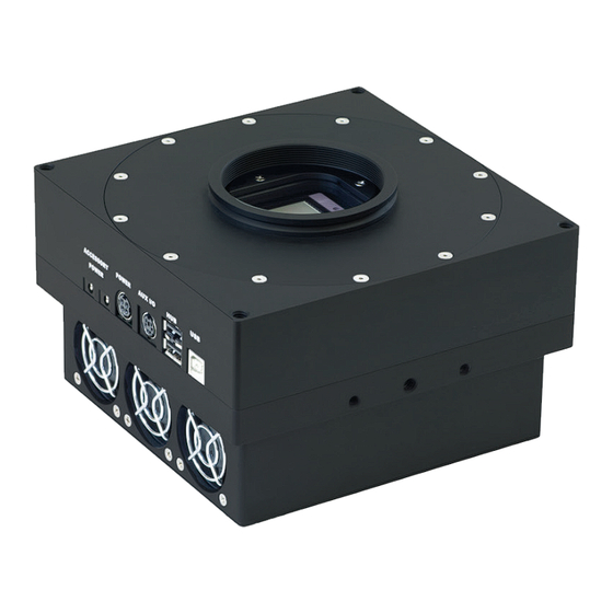
Page 5: Proline Imaging System Overview
ProLine Imaging System Overview ProLine High Performance CCD Cameras set the standard in key performance areas that include: Download Speeds, Cooling, Low Noise Operation, RBI Anti-Ghosting Technology, Image Quality, and Linearity. ProLine cameras are available with a wide variety of sensors that include full-frame front illuminated, full-frame back illuminated, frame transfer and interline. -
Page 6: System Accessories
All of our focusers are ASCOM compliant. Additional information about the Focuser is available in a separate document, “Focuser User’s Guide” that is supplied with this product. FLI stocks a large variety of adapters for the most popular telescopes. If you do not find what ►... -
Page 7: Proline Imaging System Connections
ProLine Imaging System Connections 12V accessory power out USB 2.0 Interface USB 2.0 Hub 12V power supply in 6 pin DIN Auxillary I/O © Finger Lakes Instrumentation, LLC. ProLine Rev Ib. Jan 2015... -
Page 8: Setting-Up And Powering Your System
Assemble all System components in one area before beginning this set up procedure. The image below depicts an assembled System. Note: Run the FLI Software Installation Kit before you set up and power your system to ensure the system recognizes and correctly initialized the camera. USB Cable Your Computer 120V A.C. -
Page 9: Installing The Fli Software Installation Kit
Onscreen prompts will indication subsequent steps and its completion. Note: If an earlier version of the FLI Software is installed on your computer, uninstall/remove it by following the onscreen prompts. Then install the most current version. Overwriting an old file is not recommended Note: Your camera may be enabled with more than one mode or speed. -
Page 10: Video Mode Setup
Video Mode Setup You can use cameras with interline sensors to focus and center an image in near real-time using FLI Grab. If you are using 3rd party software refer to its documentation for a similar feature. To use video mode Setup the camera with power and the USB cable as described earlier in this guide. -
Page 11: Appendix A - External Triggering
Appendix A - External Triggering The ProLine Imaging Systems has a six pin connector shown in the image below. Pin 6 is the electrical ground. Pin 5 is the logic input for the external trigger. (This input has a 22.1K pullup resistor to +3.3V). -
Page 12: Shutter Open Indicator-12
Shutter Open Indicator Pin 2 on the AUX I/O connector provides an LVTTL compatible signal for shutter open indication. When the shutter is opened, pin 2 is pulled to +3.3V through an internal 22.1Kohm resistor. When the shutter is closed, pin 2 is pulled down to ground through a 332-ohm resistor within the camera. Pin 6 is the ground reference for this signal. -
Page 13: Filter Wheels-13
5. PL OBFD = Optical back focal distance (image plane of CCD to cover side of fi lter wheel) for PL or ML camera with 65 mm shutter. See note 14. 6. ML OBFD = OBFD for standard 25mm or 45mm MicroLine with FLI dovetail + fi lter wheel. See note 14. -
Page 14: Appendix C - Troubleshooting
Appendix C – Troubleshooting Issue Remedy Check that the camera is plugged into a suitable The fan on the camera does not turn. power supply and that power is available. The fan turns but when I use FLIGrab, but the camera does Make certain that all cables are well seated and are not stretched. -
Page 15: Appendix D - Warranty For Fli Products
Incidental and consequential damages resulting from the use of FLI products, malfunction or failure to perform, or lack of fitness for a particular purpose, are not the responsibility of FLI and are hereby excluded both for property damage and to the extent permitted by law, for personal injury damage. -
Page 16: Appendix E - Fli Return Procedure
Add additional packing material around the sides of each item(s) and on top of the item(s). Write a letter that includes the following: reason the item is being returned to FLI or distributor, your complete contact information (name, phone number(s), email address, return shipping address), and if appropriate, payment method and information. -
Page 17: Return Addresses By Carrier
Return Addresses by Carrier UPS and Fed Ex Returns Finger Lakes Instrumentation Att. Greg Terrance 7287 West Main St. Lima, N.Y. 14485 USPS Returns Finger Lakes Instrumentation Att. Greg Terrance P.O. Box 19A 7298 West Main St. Lima, N.Y. 14485 ©... -
Page 18: Appendix F - Four Conductor Power Cable (Pt1)
If the polarity of the power connection is reversed it can cause damage to the camera. This damage will not be covered by the FLI product warranty. Verify the polarity of the voltage using a meter before attaching a power cable to the camera. Also verify the chosen system has the same current capability. -
Page 19: Appendix G - Liquid Cooling Options
The following connection fittings are currently available: Connector Standard User Interface Additional Information FLI recommends use of hose clamps. User supplies tubing and 1/8” ID Hose Barb 1/8” ID Tubing clamps with appropriate pressure rating for their application FLI supplies both female and male connectors,...
Need help?
Do you have a question about the ProLine Imaging System and is the answer not in the manual?
Questions and answers