
Summary of Contents for DADISICK DS Series
- Page 1 USER'S MANUAL LONG DISTANCE LASER RANGEFINDER DS series DONGGUAN DADI ELECTRONIC TECHNOLOGY CO., LTD We rese e the right to make technical changes 2024-11-09 sale@dadisick.com Website: www.dadisick.com Email:...
-
Page 2: Table Of Contents
DS Series Long Distance Sensor Software User Manual Table of contents 1 About this document..........................5 2 Safety information............................. 6 3 Function and structure..........................8 3.1 Basic functions............................. 8 3.2 Structure............................... 8 3.3 Indicator elements and operating elements..................9 3.4 LED indicators............................9 3.5 LED display............................ -
Page 3: About This Document
This document describes the installation, con guration and use of the long- distance laser range nder DS-120 produced by Dongguan Dadi Electronic Technology Co., Ltd. (hereinafter referred to as "DADISICK”), including but not limited to: safety information, functions, mechanical installation, electrical installation, network con guration, equipment operation, host computer software operation, etc. -
Page 4: Safety Information
■ It is prohibited to use the device in explosive or corrosive environments and extreme environmental conditions. ■ The use of accessories without the express written permission of DADISICK Optoelectronics shall be at your own risk. Network Security The operation of DS-120 can be completed through the software provided by Dadi Electronics. - Page 5 DS Series Long Distance Sensor Software User Manual ■ Basic knowledge of the computer operating system used ■ Basic knowledge of establishing and setting up connections Debugging, parameter con guration and inte aces ■ Basic knowledge of data transmission ■ Knowledge of equipment operation and operation in the...
-
Page 6: Function And Structure
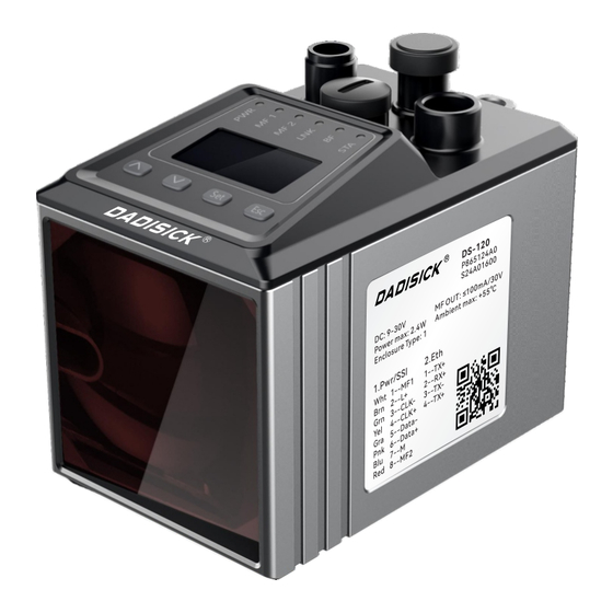
DS Series Long Distance Sensor Software User Manual 3 Function and structure 3.1 Basic function DS-120 consists of a laser, an optical receiver, and a built-in processing circuit system and software system. The sensor emits a light beam, which is re ected by the re ector to the optical receiver. -
Page 7: Indicator Elements And Operating Elements
DS Series Long Distance Sensor Software User Manual Note: ① Fastening thread M5 ② Device zero point ③ Transmitter optical axis ④ Receiver optical axis ⑤ Bolt hole for star handle of calibration bracket ⑥ Locking hook of calibration bracket ⑦... -
Page 8: Led Display
DS Series Long Distance Sensor Software User Manual Ethernet po 1 connection status (Link) (red, green, blue) ■ LED ashes blue: data exchange is active ■ LED green: connection with external device (Link) ■ LED red: no connection with external device (Link) Multifunctional input/output terminal MF1 (blue) ■... - Page 9 DS Series Long Distance Sensor Software User Manual Measurement value display After sta up, the device is in the measured value display operating mode. The RUN icon and the current distance value are displayed. Menu Display The MEN icon is displayed in the menu display operating mode. In this operating mode, device parameters can be read or set via the inte ace.
-
Page 10: Operating Buttons
DS Series Long Distance Sensor Software User Manual 3.6 Operation buttons Operate Button ■ Select menu, parameter or page downward ■ Decrease value ■ Select menu, parameter or page upwards ■ Increase value ■ Enter menu mode ■ Switch to the next menu level ■... -
Page 11: Assembly
DS Series Long Distance Sensor Software User Manual 4 Assembly 4.1 Installation process 1. Determine the mounting position while obse ing the installation instructions, see "Notes". 2. Select and install the re ector, see "Select and install the re ector". -
Page 12: Arranging Multiple Distance Sensors
DS Series Long Distance Sensor Software User Manual Re ector inclination To avoid direct su ace re ections: Mount the re ector at an angle of approx. +1° … +3° on 2 coordinate axes (horizontal or ve ical). ■ Shiny su aces parallel to the laser beam axis can cause beam de ection or scattered light, which can lead to measurement errors. - Page 13 DS Series Long Distance Sensor Software User Manual Co-directional beam Note: ①Distance sensor ②Re ector H: minimum distance Smax: maximum travel distance DONGGUAN DADI ELECTRONIC TECHNOLOGY CO., LTD We rese e the right to make technical changes 2024-11-09 sale@dadisick.com Website: www.dadisick.com...
-
Page 14: Receive Level
DS Series Long Distance Sensor Software User Manual Reverse beam Note: ①Distance sensor ②Re ector H: minimum distance Smax: maximum travel distance The minimum distance calculation formula is as follows: Formula H ≥ 0.1m + 0.01 x Smax[m] Example ■ If the maximum travel distance Smax is 60 m ■... - Page 15 DS Series Long Distance Sensor Software User Manual 4.4 Reception level An accurate measurement requires the highest possible reception level. The reception level decreases as the distance increases and/or the optical contact su aces (sensor, transparent protective cover of the re ector) become increasingly di y. This means that the signal attenuation, the dB value that can be read in the main menu, increases.
-
Page 16: Electrical Installation
DS Series Long Distance Sensor Software User Manual 5 Electrical Installation Warning: Incorrect operating voltage can cause personal inju Working with power on can cause equipment damage or unexpected operation! ■ Only pe orm wiring work when the power is o . -
Page 17: Wiring Diagram
DS Series Long Distance Sensor Software User Manual 5.2 Wiring diagram 5.2.1 Working voltage wiring diagram Description Number Mark Core color white Multifunctional input and output terminal MF1, type B brown Operating voltage: +18… +30V DC Rx-/CLK- green Receive signal -/clock signal -... - Page 18 DS Series Long Distance Sensor Software User Manual 5.2.2 Ethernet wiring diagram Description Number Mark Send data signal + Receive data signal + Send data signal - Receive data signal - DONGGUAN DADI ELECTRONIC TECHNOLOGY CO., LTD We rese e the right to make technical changes 2024-11-09 sale@dadisick.com...
-
Page 19: Device Operation
DS Series Long Distance Sensor Software User Manual 6 Device operation Tips ■ Improper operation can damage the keys! This can make operation di cult or even impossible. ■ Only use your ngers or a suitable pointing device to operate the keys. -
Page 20: Ssi Menu
DS Series Long Distance Sensor Software User Manual 6.4 SSI menu This menu allows you to set parameters for the SSI inte ace. Description Parameters ■ Select the data format for the SSI inte ace. For more information on the data format, see "SSI protocol (data format)". -
Page 21: More? Menu
DS Series Long Distance Sensor Software User Manual 6.5 more? menu The more? menu allows you to enable and disable the extended menu view. Option Description ■ Enables and disables the extended menu view. When enabled, the full menu is displayed. When disabled, the MF1, Mf2, O set and SpecFu parameters are hidden. -
Page 22: Mf1 - Dist Submenu
DS Series Long Distance Sensor Software User Manual ■ Select the function of Mf1. ■ Options • Dist: MF1 will be used as a distance output signal switching device. • Speed: MF1 will be used as a speed output signal switching device. -
Page 23: Mf1 - Speed Submenu
DS Series Long Distance Sensor Software User Manual Limit: Distance switch threshold. Hyst: Hysteresis value related to the distance threshold. Dist: Measured distance. 6.9 MF1 – Speed submenu This submenu allows you to set the MF1 as a speed output signal switching device. -
Page 24: Mf1 - Se Ice Submenu
DS Series Long Distance Sensor Software User Manual Limit: The switch threshold for speed. Hyst: The hysteresis value related to the speed switch threshold. Speed: The measured speed. 6.10 MF1- S ice submenu Through this submenu, MF1 can be set as the output signal switching device for the fault to be processed. -
Page 25: Mf1 - Lsro Submenu
DS Series Long Distance Sensor Software User Manual ■ Options • On • O ■ Facto setting: On ■ MF1 is activated when the measured value is not plausible. Possible causes include internal error, hardware failure, beam break, optical inte erence or electrical inte erence. -
Page 26: Mf2 Menu
DS Series Long Distance Sensor Software User Manual Preconditions for display: ■ more? menu: Yes option. ■ MFx On menu: Enable option. ■ Functn parameter: Preset option. Description Parameter ■ Default value for the setting. When MF1 is activated, the reference value is adopted and the associated compensation value is calculated. -
Page 27: O Set Menu
DS Series Long Distance Sensor Software User Manual Depending on the selection of parameter "Functn", the corresponding Dist / Speed / submenu is displayed. For parameter descriptions, see the relevant S ice tables in the following chapters. Counts the switching events of MF2. Switching the device o and on Count again resets the counter. -
Page 28: Device Reset
DS Series Long Distance Sensor Software User Manual Description Parameter ■ Select the lter characteristic for the distance measurement. ■ Options • Slow AvgDst • Medium • Fast ■ Facto setting: Medium ■ Select the lter depth for the speed measurement (smoothing average lter). -
Page 29: Ssi Inte Ace
DS Series Long Distance Sensor Software User Manual 7 SSl inte ace 7.1 Ove iew of SSI inte ace The SSI (Synchronous Serial Inte ace) inte ace provides distance measurements of the LD100 via serial data transmission. The inte ace can transmit clock signals and data signals. -
Page 30: Dimensional Drawing
DS Series Long Distance Sensor Software User Manual 8 Dimensions 4-M5 depth 10mm Light outlet position Unit: mm (millimeter) DONGGUAN DADI ELECTRONIC TECHNOLOGY CO., LTD We rese e the right to make technical changes 2024-11-09 sale@dadisick.com Website: www.dadisick.com Email:...
Need help?
Do you have a question about the DS Series and is the answer not in the manual?
Questions and answers