
Summary of Contents for Apure A10CD
- Page 1 APURE Industrial On-line Conductivity/Resistance/TDS controller Operating Manual 12.00mA 8.00mA Measuring 1413 uS/cm Conductivity 2021-01-01 Initial password:0000 Note: please read the manual carefully before use.
-
Page 2: Safety And Precautions
Thank you for purchasing our products. In order to continuously improve the quality of the controller and the needs of enhanced functions, our company reserves the right to modify the content and icon display at any time. The actual display may be different from the operating manual, so the actual situation is subject to the machine. -
Page 3: Table Of Contents
Catalog ⅠOverview....................4 Ⅱ Combination and installation..............5 2.1 Main engine fixed(panel mounting) ........... 5 2.2 Panel mounting reference drawing..........5 2.3 Electrode mounting................6 Ⅲ Electrode and electrical wiring............. 10 3.1 Back wiring diagram..............10 3.2 Back contact function diagram............11 3.3 Backplane terminal contact description.........12 Ⅳ... -
Page 4: Ⅰoverview
ⅠOverview This controller is highly intelligent and flexible. It can measure Conductivity/Resistance/TDS and temperature at the same time. It is widely used in urben sewage treatment plants, electricity , water supply, etc. Continuous me-asurement of Conductivity/Resistance/TDS in water inthe pharmaceutical, checmials, food and other industries. Basic Function 1. -
Page 5: Ⅱ Combination And Installation
Ⅱ Combination and installation 2.1 Main engine fixed This controller can be plated, wall-mounted installation. 2.2 Panel mounting reference drawing 92.5mm 92.5mm Mounting clips Cut off dimensions 112mm 87mm 87mm Control box cut-off dimensions... -
Page 6: Electrode Mounting
2.3 Electrode mounting 2.3.1 Electrode shape and installation form KS-1 Conduvtivity sensor... - Page 7 2.3.2 Common installation methods Installation of sensors is a very careful work, please install sensors must carefully select the installation site, deliberate installation methods, so as to avoid the measurement data distortion. The electrode joint in figure A is too long, and the extension part is too short. The dead cavity is easy to be formed in the sensor, resulting in measurement error.
- Page 8 Other common wrong installation methods: The measurement error or instability can be caused by the flow cannot guarantee the full pipe or high gas accumulation. 2.3.3 Installation precautions and maintenance The flow cell should be installed in the pipeline where the flow rate is stable and it is not easy to produce bubbles.
- Page 9 Please keep the electrode measurement part clean when installed. Don't touch the surface directly with hands or dirty objects. After contact with greasy dirt, grease and glue, the accurate value can’t be measured for a longtime. The conductivity cell is a precise measuring component. It can’t be decomposed and change the shape and size of the electrode.
-
Page 10: Ⅲ Electrode And Electrical Wiring
Ⅲ Electrode and electrical wiring 3.1 Back panel wiring diagram... -
Page 11: Back Contact Function Diagram
3.2 Back contact function diagram 3.3 Backplane terminal contact description 01 REL1: First alarm control, external relay 02 REL1: First alarm control, external relay 03 REL2: Second alarm control, external relay 04 REL2: Second alarm control, external relay 05 REL3: Third alarm control, external relay 06 REL3: Third alarm control, external relay 07 NC:NC 08 AC:AC power supply 220VAC(N)/DC:24V+... -
Page 12: Alarm Output
20 Cond-ma(+):conductivity current output positive end 21Cond-ma(-):conductivity current output negative end 22 T-ma(+):Temperature current output positive end/RS485 A connector 23 T-ma(-):Temperature current output negative end 24 NC:NC /RS485 B connector Note:This instrument supports two groups of 4-20MA or one group of 4- 20mA and one group of RS485. -
Page 13: Ⅳ Panel Introduction
Ⅳ Panel introduction 4.1Panel introduction Measuring Conductivity 2021-01-01 4.2 Buttom description In order to prevent improper operation by non-users, password protection is enabled when entering parameter setting and correction, and each function is described as follows:... -
Page 14: Display Description
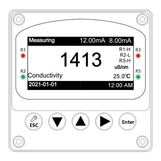
4.3 Display description In the display mode of system measurement, it will be shown as follows: Current Temp current Reading output output Relay 12.00mA 8.00mA Measuring Measuring R1-H R2-L Unit 1413 R3-H Electrode uS/cm Temperature 25℃ Conductivity Time Date 2021-01-01 09:25AM System Information Alarm Information... -
Page 15: Ⅴ Menu Introduction
Ⅴ Menu introduction According to the different functions, the controller is divided into four first-level menus, each first-level menu includes two-level or even multiple secondary menus, each menu has a number, which is easy to view and set the instrument parameters. And the secondary menu will display the setting parameters of the controller in the upper right of the screen according to the function, and the user can know the instrument parameters without entering the subordinate menu. - Page 16 Language 1. English 2. 简体中文 5.1 System Settings Menu 1.1 Language This instrument supports Chinese and English two languages, two languages can switch freely. For example: select simplified Chinese and press Enter key to confirm, the whole display interface of the instrument will be changed into simplified Chinese. Note:In order to prevent the user from misoperation, after the customer selects the parameter and presses the "Enter", there will be four prompts “ESC”, “OK”, “NO”...
- Page 17 Backlight Menu 1.4 Backlight 1.4.1 30s This instrument supports four kinds of backlight 1.4.2 60s time, the user can set the corresponding 1.4.3 120s backlight time according to the demand. The 1.4.4 Always screen will darken when the meter reaches backlight time.
- Page 18 Menu 2.3 Digital filtering Digital Filter The measured value of the meter is filtered by means of averaging, and three digital filtering methods are supported. 2.3.1 L Low point: average every 5s. 2.3.2 M Midpoint: average every 10s. 2.3.3 H High point: average every 20s.
- Page 19 parameter according to the actual situation. After pressing the Enter key to confirm, the measured value will change according to the temperature compensation parameter. Note:The temperature compensation reference temperature of the instrument is fixed at 25 °C, and the calculation formula is: Ct = C25{1+α(T-25)} C25 is COND/Resistance value at 25 °...
- Page 20 The user can freely set the hysteresis value within the range allowed by the meter and press Enter to confirm. Note: Greater than (or less than) the alarm trigger value is pulled in. Below (or greater than) the hysteresis value is released. The relay action diagram is as follows: An example of the high point mode is: High point Relay 1 mode = high point.
- Page 21 Menu 3.4.3 Current-1 Set. 20mA Current-1 Set. 20mA The user can freely set the current 20ma setting value. After pressing Enter, the system will automatically save the settings. Note:The conductivity value and current valueset in 4-20mA correspond to each other, andthe calculation formula is:...
-
Page 22: Ⅵ Calibration
Ⅵ Calibration The calibration of this control instrument is corrected by Coefficient Settings electrode coefficient, enters the 2.2 coefficient menu, selects the electrode coefficient of the electrode as (1.0 coefficient), dips the electrode into the correction liquid (such as 1413uS/cm). Coefficient Settings Adjust the value of the electrode coefficient by button (such as adjusting the... -
Page 23: Ⅶ Default Factory Setting
Ⅶ Default Factory Settings Menu name Range setting Factory default Measurement uS/cm / MΩ.cm uS/cm unit Digital filtering Low/middle/high point Low point Temperature PTC/NTC/Manual Manual compensation Manual 0.0 ~ 100.0 ℃ temperature 25.0 ℃ compensation High alert trigger 0.00 ~ 20.00 15.00 uS/cm uS/cm... -
Page 24: Maintanance
Maintenance Possible factors Check method The power is not on. A. Check for 220V voltage Meter fault. between (01) (03) 1.Without display B. Request professional maintenance. A. Check the cables The electrode wiring B. Pipeline rectification or is wrong. alternative measurement points Bubbles in the line 2.Instability of... -
Page 25: Modbus Rtu Communication Protocol
Modbus RTU Communication Protocol Conductivity, Resistance... - Page 26 Example: Reading Sending command(Hexadecimal) Note:Floating-point data is a 32-bit IEEE754 format above the table as an example, divided into two 16-bit register data transmission, the last16-bit register(0000)first pass,the first 16-bit register(40 E0)data pass, each16-bit format highrt is first, lower is after. For example, now that Conductivity is 7.00, the 16-step of floating points is displayed as 40E00000, and the transfer order is 000040E0.
- Page 27 Unusual response format description: If the sensor does not perform the upper computer command correctly, the following format information is returned: a)CODE: 01-Illegal function code 02-Illegal data address bit 03-Illegal data b)COM:The received function code uS/cm M /cm Minute pH-TI...
Need help?
Do you have a question about the A10CD and is the answer not in the manual?
Questions and answers